Two-degree-of-freedom hinged joint with single-direction return function

A hinged joint and degree of freedom technology, applied in the direction of pivot connection, etc., can solve the problems of uneven force on the shaft installation hole, lack of spring automatic reset function, and increased difficulty in fixing the wire rope and joint, so as to improve the bearing capacity Effect

Inactive Publication Date: 2013-01-16
NANJING UNIV OF AERONAUTICS & ASTRONAUTICS
View PDF7 Cites 2 Cited by
  • Summary
  • Abstract
  • Description
  • Claims
  • Application Information

AI Technical Summary

Problems solved by technology

This hinged joint has several defects: it only has two degrees of freedom of rotation, and it does not have the function of spring automatic reset. When the capture mechanism repeats its work many times, it often occurs that the wire rope cannot return smoothly to the groove on the inner wall of the ring; The mechanism has very strict requirements on the length of t

Method used


Image

  • Two-degree-of-freedom hinged joint with single-direction return function
  • Two-degree-of-freedom hinged joint with single-direction return function

Examples


Embodiment Construction

[0014] specific implementation plan

[0015] Basic principle of the present invention:

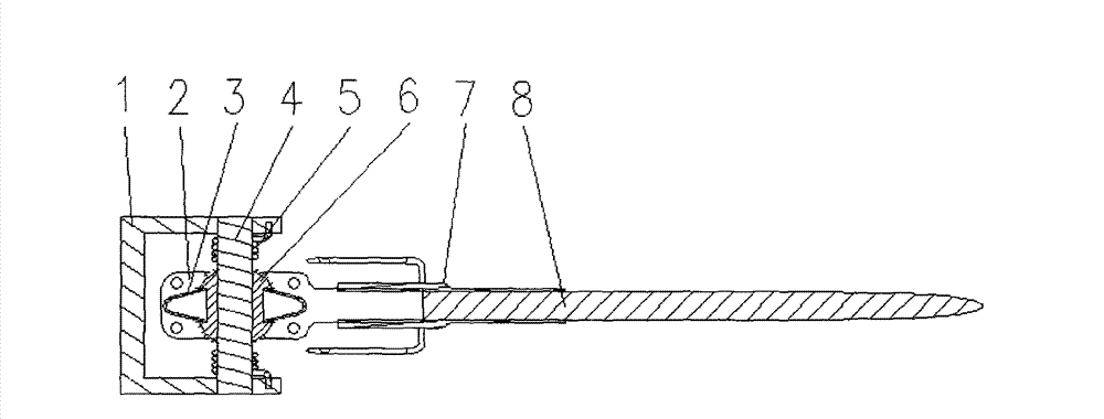
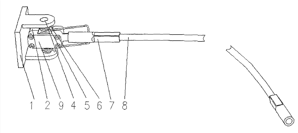
[0016] 1. If figure 1 As shown, when the steel wire rope rotates in a direction perpendicular to the paper surface, the slotted cylinder 6 rotates around the rotation axis 4, and there is no relative movement between the slotted cylinder 6 and the shell 2, and the part of the metal sleeve 7 installed on the elongated section of the shell is forced to twist The spring 5 twists to generate torsion. When the force driving the rotation of the steel wire rope 8 disappears, the torsion force of the torsion spring 5 forces the shell 2 to drive the slotted cylinder 6 to rotate toward the initial position to realize reset;

[0017] 2. If figure 1 As shown, when the wire rope rotates parallel to the paper surface, the slotted cylinder 6 and the rotating shaft 4 are relatively stationary, and the shell 2 and the slotted cylinder 6 rotate relative to each other. Since the contact here is a cylindri...


PUM


Abstract

A two-degree-of-freedom hinged joint with a return function belongs to a wire rope connection return device for a mechanical arm tail end effector adopting a wire rope soft catching manner. The hinged joint is a two-degree-of-freedom hinged joint comprising housings (2 and 9), a centrally slotted cylinder (6), and a rotating shaft (4), wherein a return leaf spring (3) and a return torsion spring (5) form an automatic return device. The two-degree-of-freedom hinged joint is characterized in that the rotation axle centers of the hinged joint in two directions are on the same point, and the return leaf spring (3) and the return torsion spring (5) are additionally arranged on a common hinged joint, so that a wire rope (8) connected with the hinged joint can return to an initial position automatically after rotation.

Description

technical field [0001] The invention belongs to a wire rope connection reset device of a mechanical arm end effector adopting a wire rope soft capture method technical background [0002] In the field of aerospace, there is a mechanical arm end effector, which uses three wire ropes to rotate each other to achieve soft capture of the adapter. The two ends of each wire rope are respectively hinged on two concentric rings that can rotate relative to each other. In the initial state, the three wire ropes are evenly distributed in the inner groove of the ring and are close to the inner wall of the ring. When the two rings rotate relative to each other, The steel wire rope rotates in a plane approximately perpendicular to the axis of the ring, and the space surrounded by the three steel wire ropes gradually shrinks, finally completing the grabbing of the large end of the adapter rod section. When the end effector capture mechanism is reset, the wire rope is required to return to ...

Claims


Application Information

Patent Timeline
IPC IPC(8): F16C11/12
Inventor 陈金宝邓飞聂宏陈萌曾占魁博伟杨铭波陈传志
Owner NANJING UNIV OF AERONAUTICS & ASTRONAUTICS
Why Eureka
Try Eureka