
Sintering furnace and net belt

A technology of sintering furnace and mesh belt, applied in the field of sintering furnace and mesh belt, can solve the problems of reducing conversion efficiency, reducing contact area, aluminum thorn, etc., to achieve the effect of improving conversion efficiency

Inactive Publication Date: 2013-01-16
JETION SOLAR HLDG
View PDF4 Cites 3 Cited by
  • Summary
  • Abstract
  • Description
  • Claims
  • Application Information

AI Technical Summary

Problems solved by technology

When the silicon wafer is placed on the mesh belt for sintering, the silicon wafer will bend to a certain extent, so that only the back electric field on both sides of the silicon wafer will contact the mesh belt, which greatly reduces the contact area, and because the mesh belt is too close to the silicon wafer, it will It affects the normal heating of the silicon wafer by the equipment, making the back electric field heated unevenly and reducing the conversion efficiency
[0004] In addition, the sintering temperature of the silicon wafer is in the range of 800-900°C, which is significantly higher than the melting point of aluminum on the back electric field. At the same time, due to the flow of gas in the sintering furnace, the silicon wafer will vibrate during sintering. The process will be tilted, which will cause the local position of the back electric field of the silicon wafer to contact the mesh belt first and damage the back electric field, thereby forming aluminum grooves and aluminum spines.

Method used


Image

  • Sintering furnace and net belt
  • Sintering furnace and net belt
  • Sintering furnace and net belt

Examples


Embodiment Construction

[0028] In order to make the above objects, features and advantages of the present invention more comprehensible, specific implementations of the present invention will be described in detail below in conjunction with the accompanying drawings.

[0029] In the following description, a lot of specific details are set forth in order to fully understand the present invention, but the present invention can also be implemented in other ways different from those described here, and those skilled in the art can do it without departing from the meaning of the present invention. By analogy, the present invention is therefore not limited to the specific examples disclosed below.

[0030] The present invention is described in detail in conjunction with schematic diagrams. When describing the embodiments of the present invention in detail, for the convenience of explanation, the cross-sectional view showing the device structure will not be partially enlarged according to the general scale, ...


PUM

PropertyMeasurementUnit
Lengthaaaaaaaaaa
Lengthaaaaaaaaaa

Abstract

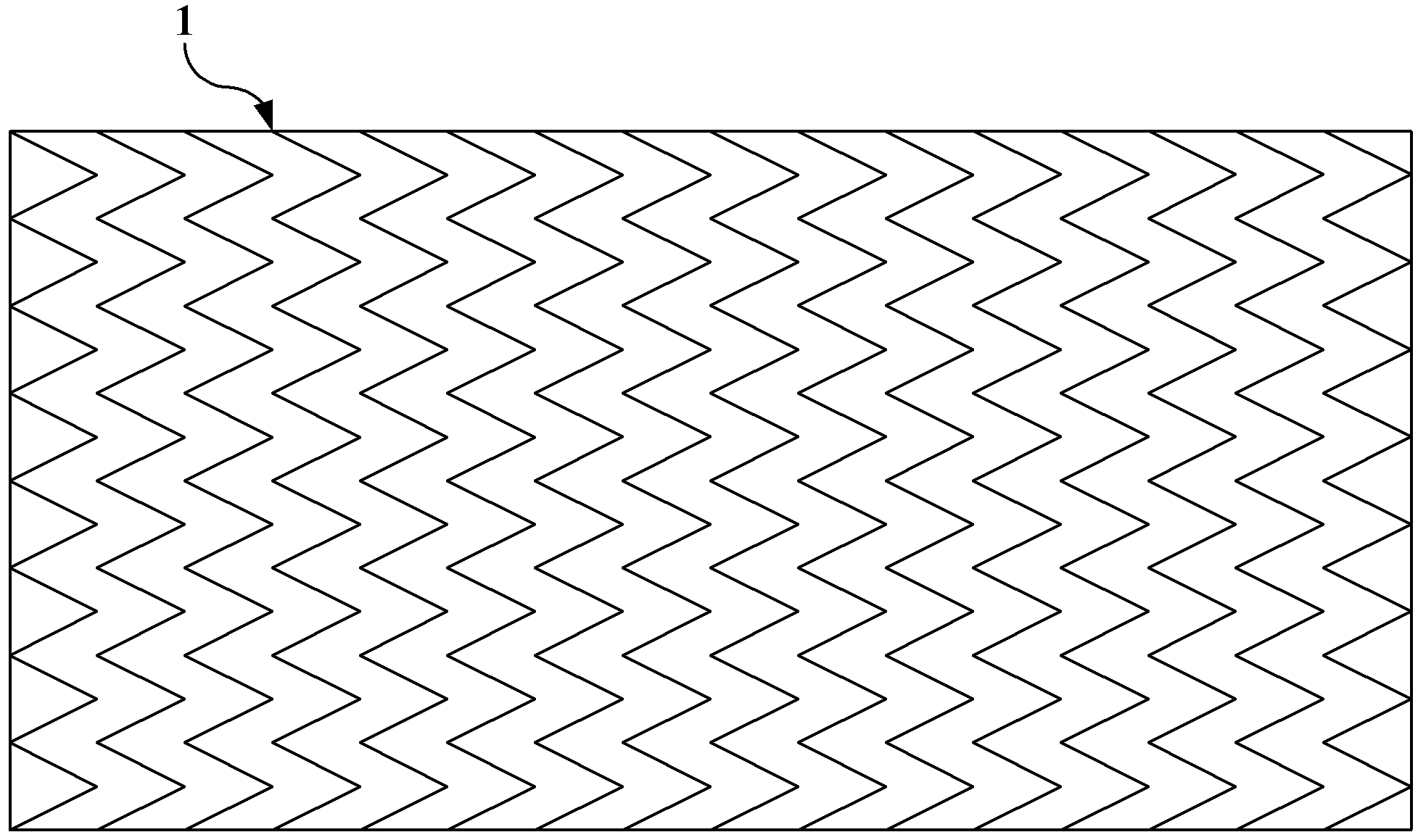
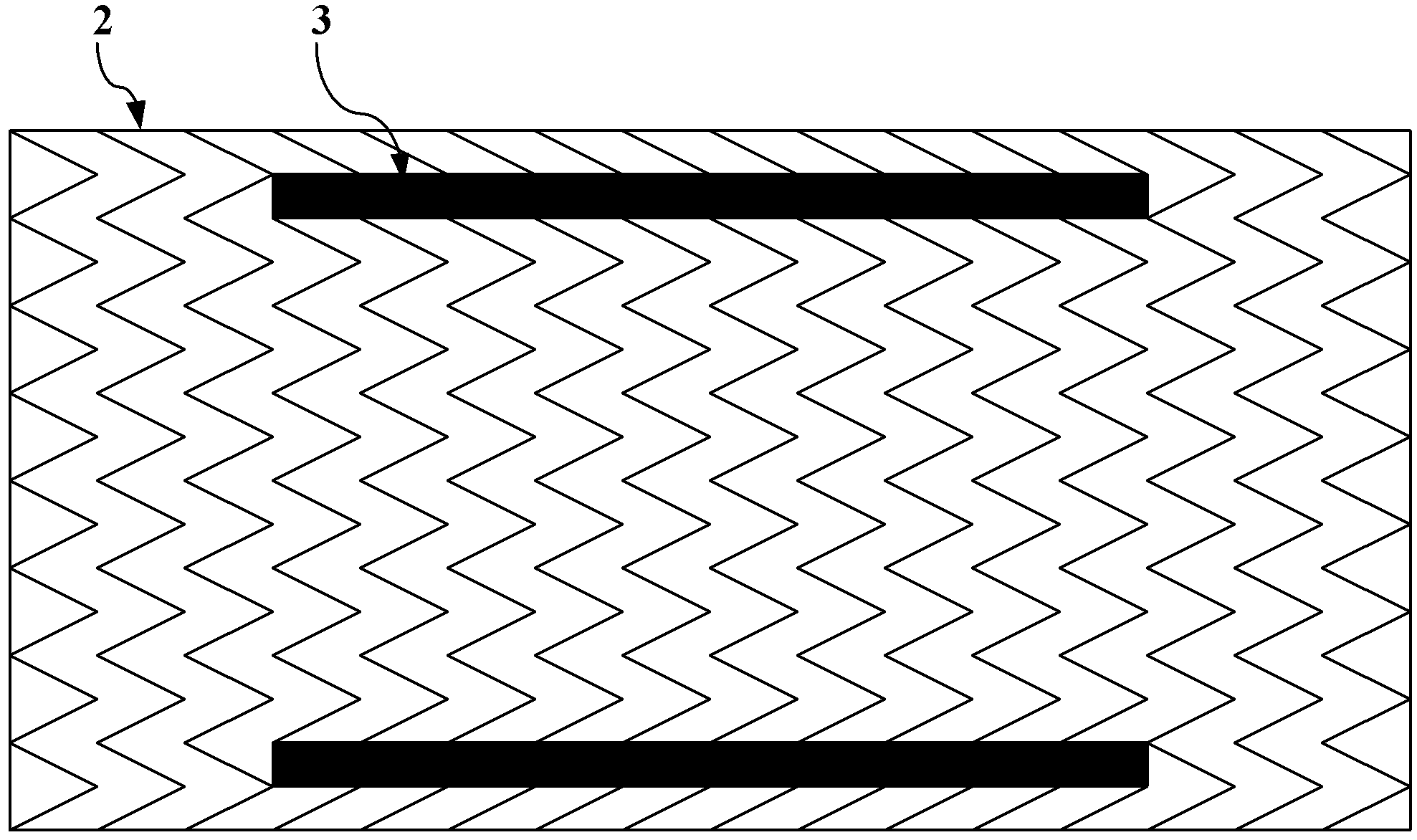
The embodiment of the invention discloses a net belt, which comprises a net belt body (2); a plurality of support body sets are mounted on the net belt body (2); each support body set comprises at least two support bodies (3); the support bodies (3) are provided with radian; and two ends of the support bodies (3) are far from the net belt body (2). According to the net belt provided by the embodiment of the invention, the support body sets are mounted on the net belt body, each support body set comprises at least two support bodies which are provided with radian, and the two ends of the support bodies are far from the net belt body, during the sintering of a silicon wafer in the sintering furnace, the silicon wafer can be bent and forms upwards radian; the support bodies in the support body sets have a certain radian, so that the edge of the silicon wafer is always contacted with the net belt, moreover, a certain distance is always kept between the net belt and a battery piece, thus, the battery piece can be prevented from non-uniform heating, and as a result, the conversion efficiency can be improved.

Description

technical field [0001] The invention relates to the field of solar cell equipment, more specifically, to a sintering furnace and a mesh belt. Background technique [0002] At present, in the production process of solar cells, the back electrode is generally printed with silver paste, and the silver paste or silver-aluminum paste is printed on the back of the silicon wafer through screen printing, and then dried; the back electric field is printed with aluminum paste, and the aluminum paste is printed by screen printing Printed on the back of the silicon wafer, after printing, the collection efficiency of photogenerated carriers can be improved in the back electric field, and then dried; sintered in a chain sintering furnace. [0003] Among them, the above-mentioned chain-type sintering furnace is generally divided into six temperature zones, the first four temperature zones are low-temperature zones, and the last two temperature zones are high-temperature zones. Glass frit ...

Claims


Application Information

Patent Timeline
IPC IPC(8): F27B9/30H01L31/18
CPCY02P70/50
Inventor 王守志
Owner JETION SOLAR HLDG
Learn More