Visual measuring device and visual measuring method for coordinates of surface of target based on round light spot marks

A technology of visual measurement and measurement method, which is applied in the direction of measuring device, photogrammetry/video metrology, optical device, etc., can solve the problems of large manual participation, change of measured surface characteristics, low efficiency, etc., and achieve simple structure, The effect of improving work efficiency and accuracy

Active Publication Date: 2013-01-16
HARBIN INST OF TECH
View PDF5 Cites 19 Cited by
  • Summary
  • Abstract
  • Description
  • Claims
  • Application Information

AI Technical Summary

Problems solved by technology

[0006] The purpose of the present invention is to solve the defects of large manual participation in the calibration process, low efficiency, and may cause changes in the characteristics of the measured surface in the current surface coordinate measurement of large structu

Method used


Image

  • Visual measuring device and visual measuring method for coordinates of surface of target based on round light spot marks
  • Visual measuring device and visual measuring method for coordinates of surface of target based on round light spot marks
  • Visual measuring device and visual measuring method for coordinates of surface of target based on round light spot marks

Examples


specific Embodiment approach 1

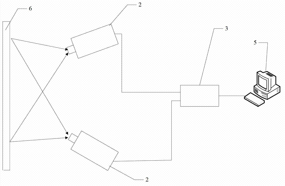
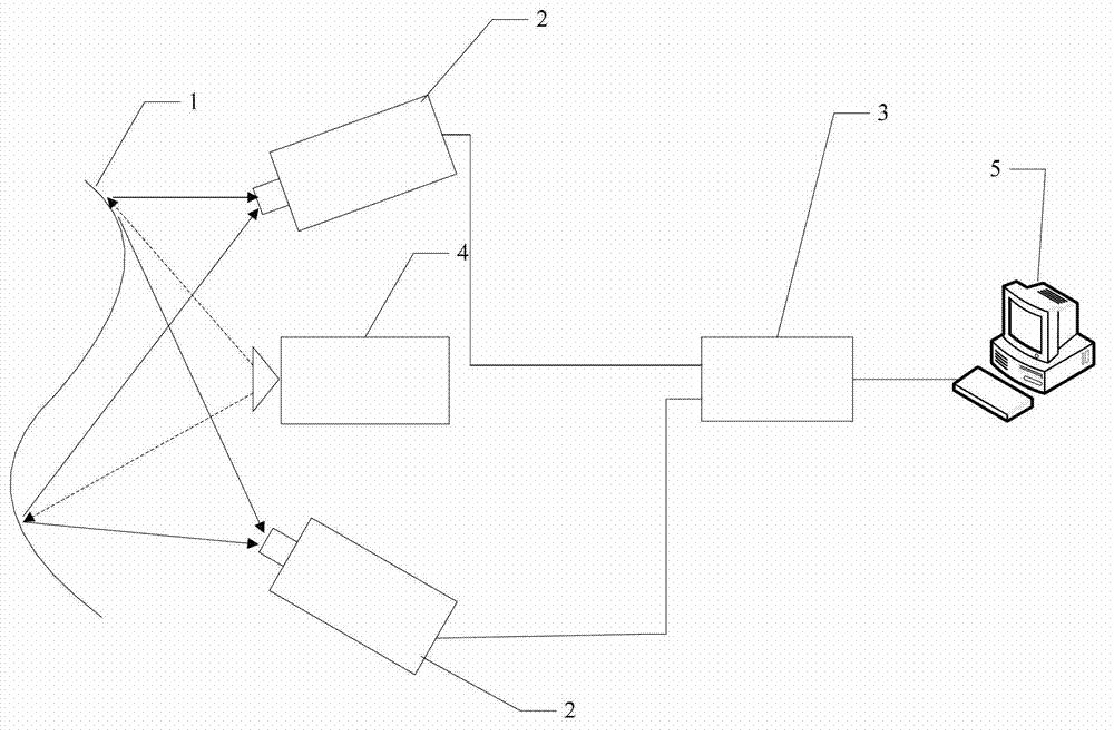
[0029] Specific implementation mode 1. Combination figure 1 and figure 2 Describe this specific embodiment, the visual measurement device based on the target surface coordinates of circular spot mark, it is made up of two visual image sensors 2, visual image acquisition device 3, projector 4 and circular spot array target 6;

[0030] The image projection lens of the projector 4 faces the surface 1 of the measured object;

[0031] The image acquisition lenses of the two visual image sensors 2 are all towards the circular spot array target 6 or the surface 1 of the measured object, and the image data output ends of each of the visual image sensors 2 are respectively connected to the two images of the visual image acquisition device 3 The data input end is connected, and the image data output end of the visual image acquisition device 3 is connected with the image data input end of the remote control center 5 .

[0032] Said two visual image sensors 3 and projector 4 are arran...

specific Embodiment approach 2

[0037] Specific embodiment two, this specific embodiment is the measurement method of the visual measuring device based on the target surface coordinate of circular spot mark according to specific embodiment one:

[0038] The measuring method of the visual measuring device based on the coordinates of the target surface marked by the circular light spot, its steps are as follows:

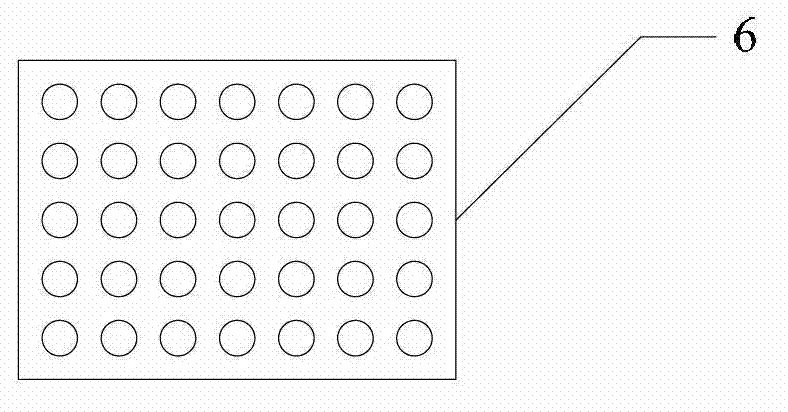
[0039] Step 1: Calibration stage: the image acquisition lenses of the two visual image sensors 2 are all directed towards the circular spot array target 6, and the distance from the image acquisition lens of the visual image sensor 2 to the circular spot array target 6 is less than 1 meter;

[0040] Step 2: adjust the positions of the two visual image sensors 2 respectively, so that the image acquisition lenses of the two visual image sensors 2 are aligned with the same measurement area on the circular spot array target 6, and the circular spot array target 6 is evenly and clearly distributed on both ...


PUM


Abstract

The invention provides a visual measuring device and a visual measuring method for coordinates of a surface of a target based on round light spot marks, and relates to the field of machine visual measurement. Shortcomings that during measurement of coordinates of the surface of the conventional large structure, manual intervention in a calibration process is high, efficiency is low, characters of a measured surface are also changed possibly, and the like are overcome. The visual measuring device comprises two visual image sensors, a visual image acquirer, a projector and a circular spot array target, wherein an image lens of the projector faces the surface of an object to be measured; image acquiring lenses of the two visual image sensors face the circular spot array target or the surface of the object to be measured; image data output ends of the visual image sensors are respectively connected with two image data input ends of the visual image acquirer in a one-to-one correspondence manner; and an image data output end of the visual image acquirer is connected with an image data input end of a remote control center. The visual measuring device and the visual measuring method can be widely used for visual measurement of coordinates of a low-frequency fluctuated surface of a large-size structure.

Description

technical field [0001] The invention relates to the field of machine vision measurement, and relates to the space coordinate measurement of the low-frequency undulating surface of a large-scale object. Background technique [0002] With the rapid development of science and technology, large-scale structures with low-frequency undulating surfaces have been widely used in modern high-tech fields, such as the surface of large aircraft fuselages, solar sails, and large-scale film antennas. At present, the methods and systems used for surface measurement of large workpieces mainly include three-coordinate machine measurement systems, theodolite measurement systems, and laser tracking measurement systems. These measurement methods are generally expensive, and due to the point-by-point scanning and contact measurement methods, the measurement efficiency is low, and they are not suitable for the measurement of weak rigid structures such as solar sails. [0003] Stereo vision Binocu...

Claims


Application Information

Patent Timeline
IPC IPC(8): G01B11/24G01C11/00
Inventor 刘炳国刘国栋陈凤东唐烽庄志涛
Owner HARBIN INST OF TECH
Why Eureka
Try Eureka