Equal thickness interference method based centering error measuring device

A measuring device and center error technology, applied in the field of optical measurement, can solve problems such as inability to measure lenses, and achieve high precision, stable and reliable methods

Inactive Publication Date: 2013-01-16
INST OF OPTICS & ELECTRONICS - CHINESE ACAD OF SCI
View PDF5 Cites 2 Cited by
  • Summary
  • Abstract
  • Description
  • Claims
  • Application Information

AI Technical Summary

Problems solved by technology

The disadvantage of this method is obvious: only the measured surface can be measured, a

Method used


Image

  • Equal thickness interference method based centering error measuring device
  • Equal thickness interference method based centering error measuring device
  • Equal thickness interference method based centering error measuring device

Examples


Example Embodiment

[0024] The present invention will be described in detail below with reference to the accompanying drawings and specific embodiments.

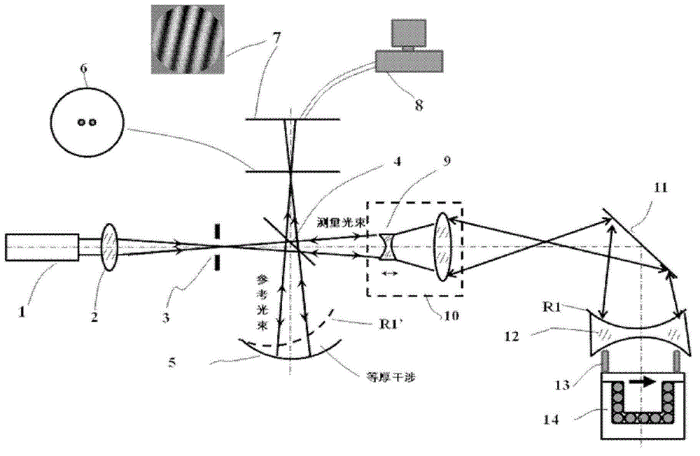
[0025] like image 3 The measuring device of the center error based on the equal thickness interferometry of the present invention is shown, including a laser 1, a converging mirror 2, a star point plate 3, a beam splitter 4, a reference mirror 5, a receiving screen 6, a CCD detector 7, a calculation group 8, Focusing group 10, refracting mirror 11, lens under test 12, connecting tool 13 and precision rotating shaft 14, wherein:

[0026] On the optical axis of the laser 1, place the converging mirror 2, the star point plate 3 and the beam splitter 4 in sequence, and the star point plate 3 is located at the focal point of the converging mirror 2; The filtering of the plate 3 forms a filtered beam, which reaches the beam splitter 4 and is split into a reference beam and a measurement beam.

[0027] The reference mirror 5, the receiving screen 6...


PUM


Abstract

The invention discloses an equal thickness interference method based centering error measuring device which comprises a laser device, a convergent mirror, a star tester, a spectroscope, a reference mirror, a receiving screen, a CCD (charge coupled device) detector, a computing group, a focusing group, a turning reflector, a measured lens, a connecting fixture and a precision rotating shaft. The convergent mirror, the star tester and the spectroscope are sequentially disposed on an optical axis of the laser device, the star tester is positioned on a focus of the convergent mirror, the reference mirror, the receiving screen and the CCD detector are sequentially disposed in an optical axis direction of a reference beam, the focusing group and the turning reflector are sequentially disposed on an optical axis of a measurement beam, the measured lens, the connecting fixture and the precision rotating shaft are sequentially disposed on an optical axis of the measurement beam turned by the turning reflector, and the measured lens is fixed on the precision rotating shaft through the connecting fixture. By the aid of the equal thickness interference principle, centering errors of the measured lens can be measured, and the equal thickness interference method based centering error measuring device can achieve whole-group measurement of a multi-lens group and is higher in precision than that of conventional visual microscopic measurement.

Description

technical field [0001] The invention relates to a center error measurement device, in particular to a center error measurement device based on equal thickness interferometry, and belongs to the technical field of optical measurement. Background technique [0002] For high-precision optical systems, the center error will destroy the basis of optical design - rotational symmetry, causing the actual optical axis of the optical element to deviate from the designed optical axis, destroying the aberration correction state of the optical design, thus seriously affecting the resolution of the optical system. imaging properties such as force, distortion and contrast. [0003] The centering device is used to measure and correct the center error of each optical element. At present, the self-collimation method is commonly used. For this method and device, see "Report on the Development of ZX-3 Internal Focusing Centering Device", Wang Zhaoxun, Optoelectronic Engineering, 1984, 05, pp. ...

Claims


Application Information

Patent Timeline
IPC IPC(8): G01B11/27
Inventor 马天梦李恋
Owner INST OF OPTICS & ELECTRONICS - CHINESE ACAD OF SCI
Why Eureka
Try Eureka