
Optical imaging autonomous navigation semi-physical simulation testing system for deep space exploration proximity process

A semi-physical simulation and optical imaging technology, applied in measurement devices, instruments, etc., can solve the problems of high cost, high risk, and no autonomous navigation ground test verification system for deep space exploration. Effect

Active Publication Date: 2013-01-16
BEIJING INST OF CONTROL ENG
View PDF4 Cites 19 Cited by
  • Summary
  • Abstract
  • Description
  • Claims
  • Application Information

AI Technical Summary

Problems solved by technology

Due to the high cost and high risk of direct flight tests, it is necessary to use ground equipment to construct a test system for semi-physical simulation test research. At present, there is no autonomous navigation ground test verification system for deep space exploration in China.
A lot of research has been done on autonomous navigation technology for deep space exploration in China, such as "A Review of Autonomous Navigation and Control Technology for Deep Space Exploration" published by Wang Dayi and Huang Xiangyu in June 2009, Volume 35, No. 3, Space Control Technology and Application , introduced the research progress of autonomous navigation for deep space exploration, but did not involve the relevant content of the corresponding ground test verification system

Method used


Image

  • Optical imaging autonomous navigation semi-physical simulation testing system for deep space exploration proximity process
  • Optical imaging autonomous navigation semi-physical simulation testing system for deep space exploration proximity process
  • Optical imaging autonomous navigation semi-physical simulation testing system for deep space exploration proximity process

Examples


Embodiment Construction

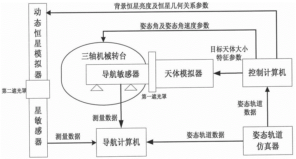
[0024] Such as figure 1 As shown, it is a schematic composition diagram of the optical imaging autonomous navigation semi-physical simulation test system of the deep space exploration approach process of the present invention. The system includes navigation sensor, star sensor, celestial body simulator, dynamic star simulator, three-axis mechanical turntable, attitude orbit simulator, navigation computer and control computer. The navigation sensor is installed on the three-axis mechanical turntable, and is docked with the celestial simulator through the first hood, and the star sensor is connected with the dynamic star simulator through the second hood, which is used to avoid laboratory stray light interference. The attitude-orbit simulator generates reference attitude and orbit data according to the dynamic model of the approaching process of the deep space probe, sends the reference data to the control computer and the navigation computer respectively, and the control comput...


PUM


Abstract

An optical imaging autonomous navigation semi-physical simulation testing system for a deep space exploration proximity process is characterized in that a navigation sensor is mounted on a rotary table to be docked with a celestial simulator, a star sensor is docked with a dynamic fixed star simulator, an attitude and orbit simulator generates deep space probe reference attitude and orbit data and transmits the data to a control computer and a navigation computer, the control computer drives the celestial simulator, the dynamic fixed star simulator and the rotary table to move, the celestial simulator simulates position changes of a deep space probe and a target celestial body, the dynamic fixed star simulator simulates inertial attitude changes of the deep space probe, the rotary table simulates attitude disturbance of the deep space probe, and the navigation computer acquires measurement data of the navigation sensor and the star sensor, performs navigation filtering computation and compares a computed result with the reference data so that autonomous navigation precision is obtained. The optical imaging autonomous navigation semi-physical simulation testing system for the deep space exploration proximity process achieves hardware-in-the-loop semi-physical simulation testing on the basis of real measurement data of the sensors and can effectively test and verify the performances of an optical imaging autonomous navigation system for the deep space exploration proximity process on the ground.

Description

technical field [0001] The invention relates to an autonomous navigation simulation test system, in particular to an optical imaging autonomous navigation semi-physical simulation test system for deep space exploration approaching process, which belongs to the technical field of autonomous navigation. Background technique [0002] Autonomous navigation technology means that the satellite can determine the position and velocity of the satellite in real time only by on-orbit measurement equipment without relying on the support of the ground system, also known as autonomous orbit determination. For satellite systems, autonomous navigation is conducive to reducing the dependence of satellites on the ground and improving the survivability of the system. Without the support of ground measurement and control stations, the determination and maintenance of orbits can still be completed, which is of great significance to the autonomous survival of satellites. very important meaning. ...

Claims


Application Information

Patent Timeline
IPC IPC(8): G01C25/00
Inventor 黄翔宇张斌王大轶魏春岭唐强朱志斌
Owner BEIJING INST OF CONTROL ENG
Learn More