
State control device for engineering structure wind tunnel model

A model state and control device technology, applied in the direction of measuring devices, non-electric variable control, control/regulation systems, etc., can solve the problems of inaccurate vertical displacement and torsion angle of the model, bulky and bulky, wide footprint, etc., to achieve The effect of simple and compact structure, high measurement accuracy and small footprint

Inactive Publication Date: 2015-08-19
SOUTHWEST JIAOTONG UNIV
View PDF7 Cites 0 Cited by
  • Summary
  • Abstract
  • Description
  • Claims
  • Application Information

AI Technical Summary

Problems solved by technology

These mechanisms and control methods have the following disadvantages: (a) the model cannot be guaranteed to move according to the preset frequency or can only achieve simple harmonic vibration, (b) the vertical displacement and torsional angle of the model are not accurate, and the vertical and torsional amplitudes Smaller, (c) can not realize vertical movement and torsional movement at the same time, can not realize the movement of arbitrary input displacement, (d) the noise is relatively large, (e) the equipment structure is complicated, bulky and heavy, and the floor area is wide

Method used


Image

  • State control device for engineering structure wind tunnel model
  • State control device for engineering structure wind tunnel model
  • State control device for engineering structure wind tunnel model

Examples


Embodiment Construction

[0021] The present invention will be further described below in conjunction with the drawings.

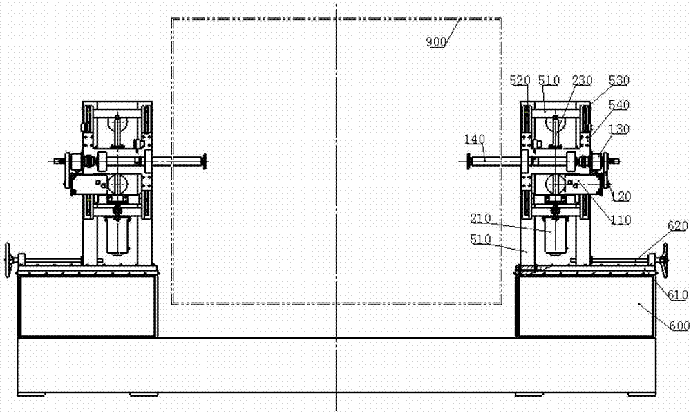
[0022] by figure 1 It can be seen that: 900 is a wind tunnel, the two model support shafts of the engineering structure wind tunnel model state control device extend into the wind tunnel, and the tested model and balance are fixed on the model support shafts. The engineering structure wind tunnel model state control of the present invention The device adjusts the state and force of the tested model and the balance through the vertical movement and axial rotation of the two model support shafts.

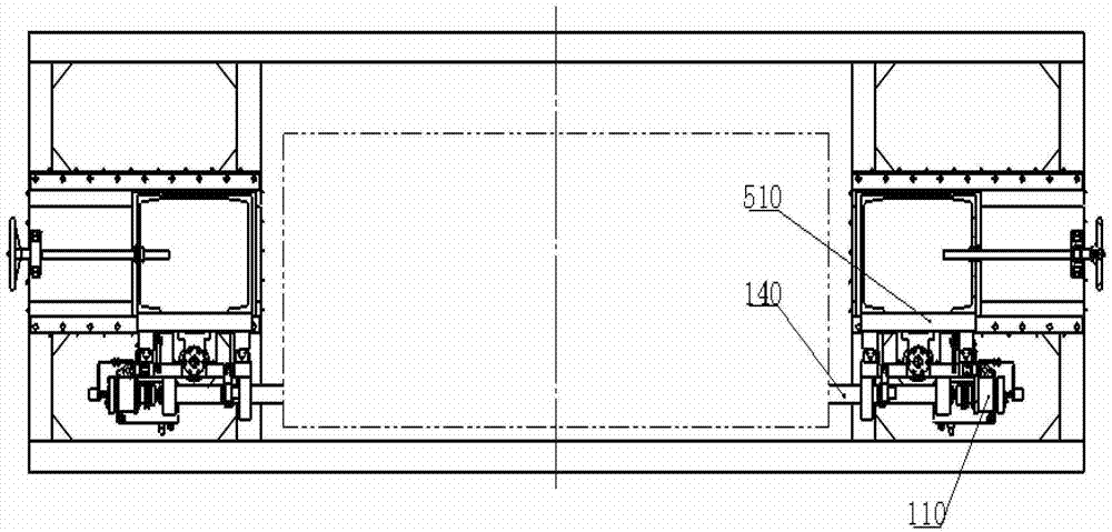
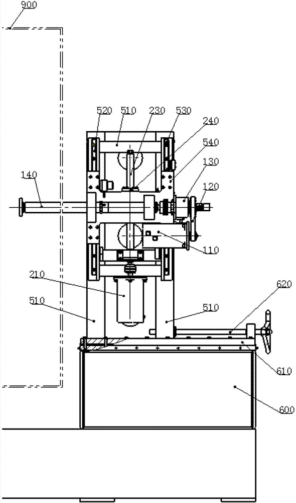
[0023] Combine Figure 1 to Figure 4 It can be seen that the control device is mainly composed of a base 600 and model supporting stands symmetrically arranged at both ends of the base. Due to the symmetry of the model support stand at both ends, the following descriptions concerning the model support stand and its components are all expanded to the model support stand on the right.

[0024] A ...


PUM


Abstract

The invention discloses a device for controlling the state of a model of a wind tunnel of an engineering structure. The device supports and controls the tested state and the vibration of the tested model in the wind tunnel and mainly comprises a base and model supporting vertical seats, wherein the model supporting vertical seats are symmetrically arranged at two ends of the base; and each model supporting vertical seat is provided with a height adjusting mechanism and an angle adjusting mechanism. The device is simple and compact in structure, simply and conveniently realizes vertical vibration, torsional vibration and coupling movement, can simulate various vibrations including random vibration, is wide in displacement and frequency range and low in manufacturing cost, and is accurate and controllable.

Description

Technical field [0001] The invention relates to wind tunnel test equipment, in particular to the manufacturing field of a state control device for a wind tunnel model of an engineering structure. Background technique [0002] Wind-induced vibrations in areas such as bridges and wings, especially flutter and buffeting, are one of the biggest factors threatening the structural safety of bridges. Among wind-induced vibrations, flutter is the most dangerous form of vibration. The flutter phenomenon is a typical aeroelastic instability. All aeroelastic instability is caused by the self-excited force acting on the structure. Therefore, the correct description of the self-excited force acting on the structure is the prerequisite and key to the study of all aeroelastic phenomena. Self-excited force refers to the aerodynamic force caused by the interaction between its own motion and the airflow on the structure immersed in the airflow. [0003] In order to describe the self-excited force ...

Claims


Application Information

Patent Timeline
Patent Type & Authority Patents(China)
IPC IPC(8): G01M9/04G05D27/02
Inventor 黄松和廖海黎王琦张文桂李明水汪永元马存明翟守才孙延国谢大帅
Owner SOUTHWEST JIAOTONG UNIV
Learn More