Endurance test device for sliding door

A durability test, sliding door technology, applied in the direction of measuring device, vehicle test, machine/structural component test, etc. The effect of reducing cylinder wear, wide range of applicable models, and strong versatility

Inactive Publication Date: 2015-04-15
SANY HEAVY IND CO LTD (CN)
View PDF7 Cites 0 Cited by
  • Summary
  • Abstract
  • Description
  • Claims
  • Application Information

AI Technical Summary

Problems solved by technology

[0005] 1. The device is only suitable for the sliding door switch durability of the linear motion guide rail, and cannot realize the sliding door switch durability of the curved motion track;
[0006] 2. The device is integral and needs to be fixed in the vehicle through the base unit, which is inconvenient for installation and debugging;
[0007] 3. The unlocking unit in the device can only realize the unlocking of the inner pulling handle on the sliding door of the car, and cannot realize the unlocking of the flapping inner opening device and the outer opening unlocking;
[0008] 4. The connection between the cylinder and the door in the device is a ball joint, which is a rigid connection, which is different from the actual use of the sliding door, which has a certain impact on the test results;
[0009] 5. There is no alarm device in the device, and it cannot be stopped in time when an abnormality occurs during the test, and there is a certain safety risk;
[0010] 6. The force direction of the unlocking cylinder is inconsistent with its axial direction during the movement, which will cause wear to the cylinder guide rod;
[0011] 7. The stroke of the door switch cylinder needs to match the stroke of the sliding door, the cost is high, and the versatility is not good

Method used


Image

  • Endurance test device for sliding door
  • Endurance test device for sliding door
  • Endurance test device for sliding door

Examples


Embodiment Construction

[0053] In order to understand the above-mentioned purpose, features and advantages of the present invention more clearly, the present invention will be further described in detail below in conjunction with the accompanying drawings and specific embodiments. It should be noted that, in the case of no conflict, the embodiments of the present application and the features in the embodiments can be combined with each other.

[0054] In the following description, many specific details are set forth in order to fully understand the present invention. However, the present invention can also be implemented in other ways than described here. Therefore, the protection scope of the present invention is not limited by the specific implementation disclosed below. Example limitations.

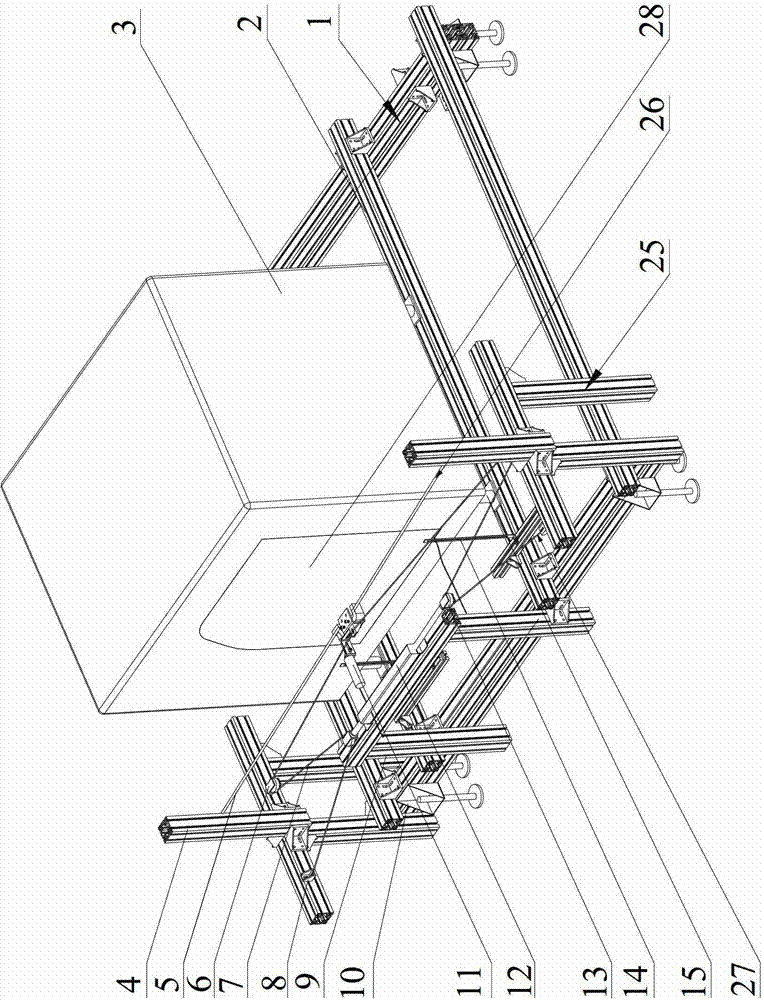
[0055] figure 1 It is a three-dimensional structural schematic diagram of an embodiment of the sliding door endurance test device according to the present invention.

[0056] Such as figure 1 As shown, the...


PUM


Abstract

The invention provides an endurance test device for a sliding door, which includes a chassis mounting bracket for fixing a tested vehicle body, an unlocking mechanism for unlocking a tested sliding door and the tested vehicle body, a flexible traction mechanism for driving the tested sliding door to move, and a control system for controlling the unlocking mechanism and the flexible traction mechanism to act. Through the adoption of the technical scheme provided by the invention, a split-type module design is adopted, the mounting is flexible, and the device can be applied to various motorcycle types; the unlocking mechanism can be mounted flexibly, and can be used for unlocking various inwardly and outwardly opened handles; the flexible traction mechanism enables the stroke of the sliding door to be free from the limit of an air cylinder, realizes the curvilinear and rectilinear motion of the sliding door, and has strong universality, and as practical hand operation can be simulated excellently, the testing rest has higher confidence level; and a man-machine interaction interface and an alarming mechanism are arranged, and enable the test device to be more reliable.

Description

technical field [0001] The invention relates to the field of engineering machinery, and more specifically, to a sliding door durability test device. Background technique [0002] At present, car doors can be divided into hinged doors and sliding doors according to the opening and closing methods. The sliding door is generally installed on the side of the vehicle body, and the door can be opened by pushing it backward to the car after being unlocked by the inward opening or outward opening handle. In actual use, the sliding door needs to be frequently operated, and its performance is not only related to the performance of the vehicle body, but also involves the life safety of the people in the vehicle. Therefore, the working reliability of the sliding door is particularly important. It is necessary to test its durability in the regular sampling inspection after it is put into production. [0003] A sliding door durability test device is disclosed in the prior art, which inc...

Claims


Application Information

Patent Timeline
Patent Type & Authority Patents(China)
IPC IPC(8): G01M17/00
Inventor 彭玉凤汪双柱曾杰
Owner SANY HEAVY IND CO LTD (CN)
Why Eureka
Try Eureka