A kind of lithography machine motion platform system and lithography machine

A technology of a lithography machine and a motion table, applied in the field of lithography, can solve the problems of poor flatness, high manufacturing difficulty and cost, and easy deformation, so as to reduce manufacturing cost and manufacturing difficulty, facilitate processing and manufacturing, and expand the scope of use. Effect

Active Publication Date: 2019-08-23
SHANGHAI MICRO ELECTRONICS EQUIP (GRP) CO LTD
View PDF4 Cites 0 Cited by
  • Summary
  • Abstract
  • Description
  • Claims
  • Application Information

AI Technical Summary

Problems solved by technology

[0005] The technical problem to be solved by the present invention is to provide a lithography machine motion table system and a lithography machine that solve the problems of manufacturing difficulty and high cost, poor flatness and easy deformation, and increase the stroke of the workpiece table at the same time.

Method used


Image

  • A kind of lithography machine motion platform system and lithography machine
  • A kind of lithography machine motion platform system and lithography machine
  • A kind of lithography machine motion platform system and lithography machine

Examples


Embodiment 1

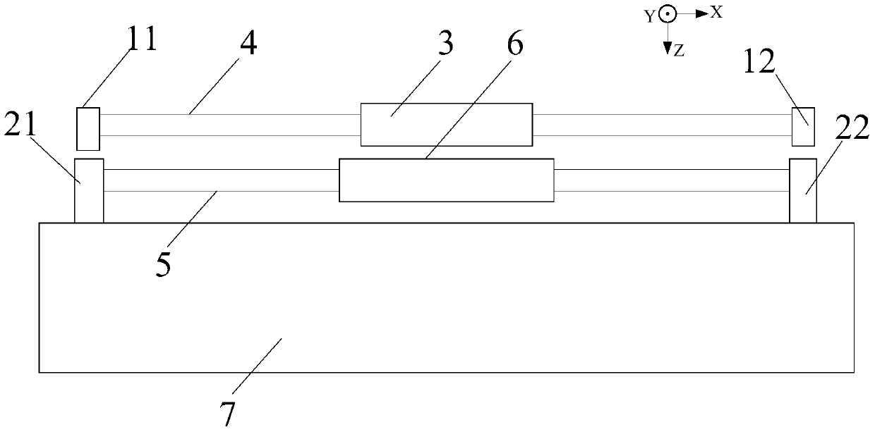
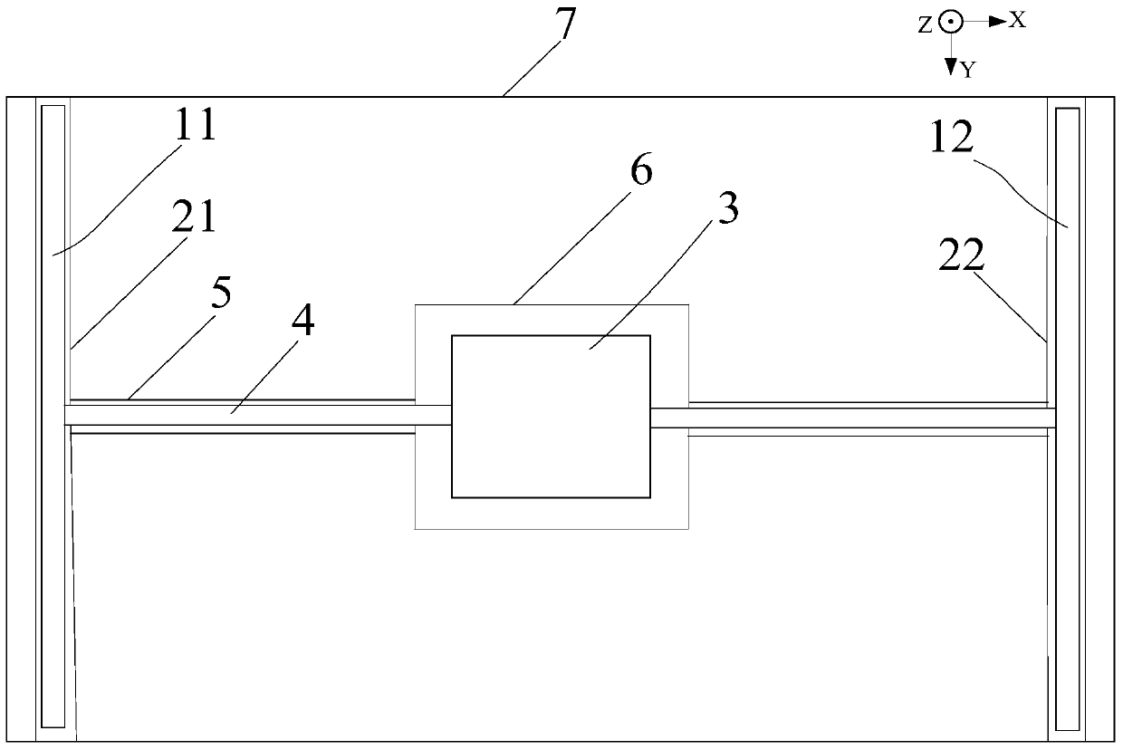
[0031] Such as figure 1 and figure 2 As shown, the lithography machine moving table system of this embodiment includes a base table 7 and a workpiece table 3 located above the base table 7, and also includes a The follow-up table 6 is used for follow-up movement, the lower surface of the workpiece table 3 is air-floated above the follow-up table 6 , and the upper surface of the follow-up table 6 is used as the air-floating support surface of the workpiece table 3 . The workpiece table 3 is driven by a first drive unit, and the follower table 6 is driven by a second drive unit. The first drive unit drives the workpiece table 3 to move two-dimensionally on the plane of the base table 7, and the second drive unit drives the follower table 6 to perform one-dimensional or two-dimensional motion on the plane of the base table 7. sports.

[0032] In the lithography machine moving table system of this embodiment, by adding a follower table 6 that follows the work table 3 between t...

Embodiment 2

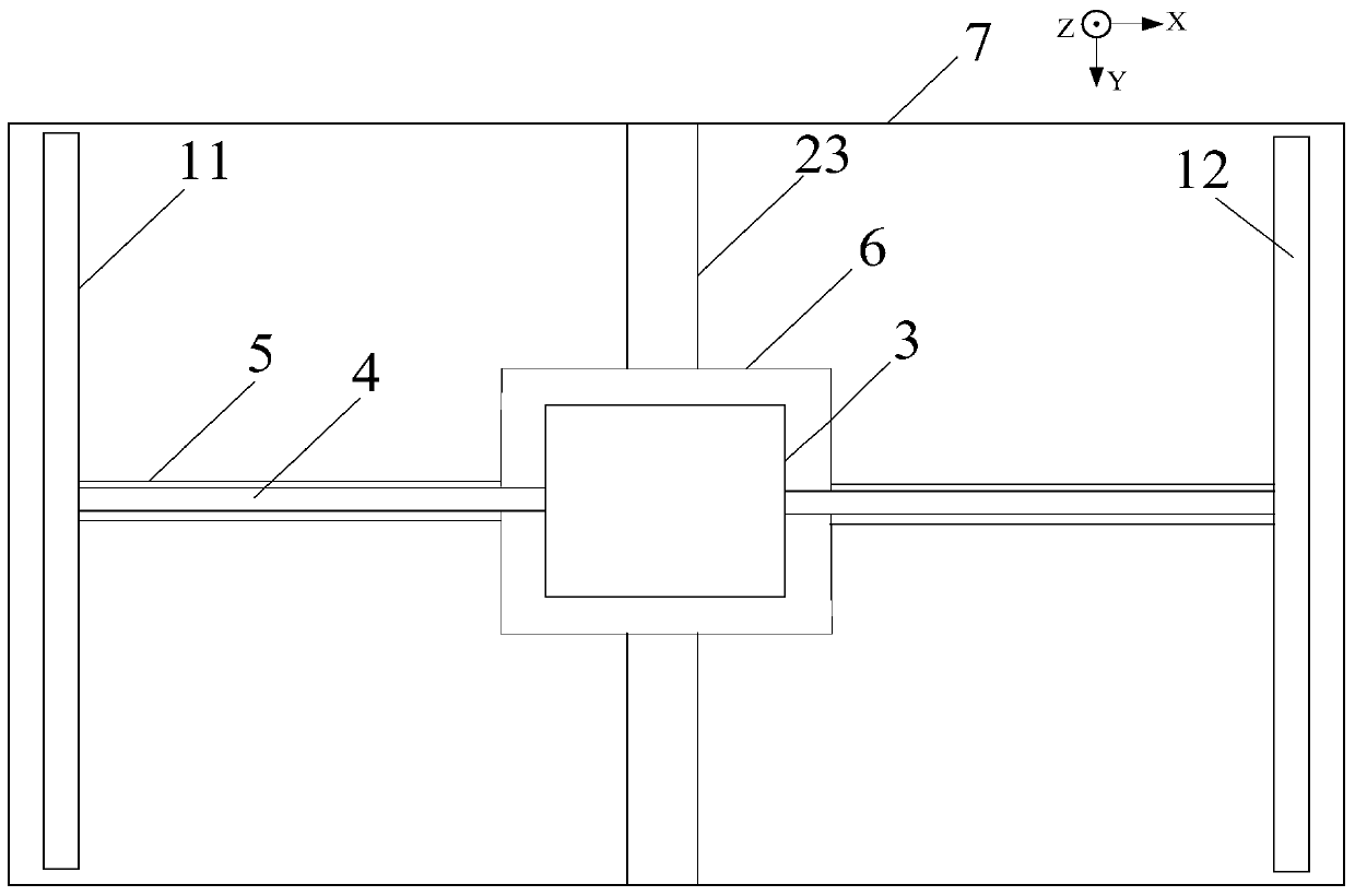
[0047] image 3 Shown is a top view of Embodiment 2 of the lithography machine moving table system of the present invention, which is different from Embodiment 1 in that the number of the Y-direction motor is one, and the fifth Y-direction motor 23 is adopted, located at the base The central position of the platform 7 forms a cross-shaped structure with the second X-direction motor 5 .

[0048] Using the above technology, compared with Embodiment 1, one Y-direction motor is reduced, the structure is simplified, and the cost of the whole system is reduced.

Embodiment 3

[0050] Figure 4 and Figure 5 Shown is a side view and an attached view of Embodiment 3 of the lithography machine moving table system of the present invention, which is different from Embodiments 1 and 2 in that the second drive unit drives the follower table 6 on the base The base 7 performs one-dimensional movement on the plane. If the stroke of the workpiece table 3 in the X-axis is not less than the stroke in the Y-axis, the second drive unit omits the Y-direction motor and uses a third X-direction motor 81 and the fourth X-direction motor 82, the follow-up table 6 is arranged on the movers of the third X-direction motor 81 and the fourth X-direction motor 82, and the width of the follow-up table 6 in the Y axis is greater than or equal to the workpiece table 3 Travel range on the Y axis. The third X-direction motor 81 and the fourth X-direction motor 82 are symmetrically arranged, and are arranged on both sides of the base platform 7 along the X-axis, and are mutually...


PUM


Abstract

The invention discloses a photoetching machine moving table system and a photoetching machine. The photoetching machine moving table system comprises a substrate table, a workpiece table positioned above the substrate table, and a servo table arranged between the substrate table and the workpiece table, wherein the upper surface of the servo table always serves as the gas floatation supporting surface of the workpiece table. Through the technical scheme provided by the invention, the servo table performing a servo motion on the workpiece table is additionally arranged between the substrate table and the workpiece table, the upper surface of the servo table serves as the gas floatation supporting surface of the workpiece table, and a large-area gas flotation supporting surface does not need to be processed even if the workpiece table is a large-stroke workpiece table, so that the stroke of the gas flotation type workpiece table is not limited, and the using range is greatly expanded; moreover, due to the fact that the area of the servo table is limited, the processing and manufacturing are easier, required flatness and rigidity of the gas flotation supporting surface can be completely reached, and the manufacturing cost and manufacturing difficulty can be effectively reduced particularly in the field of large-stroke workpiece tables.

Description

technical field [0001] The invention relates to a lithography machine moving table system and a lithography machine, which are applied in the technical field of lithography. Background technique [0002] Microelectronics technology is a new technology developed along with integrated circuits, especially VLSIs. Microelectronics technology is the core technology of high-tech and information industry. It has penetrated into various fields of modern technology and social life. The rapid development of microelectronics technology has changed the appearance of modern social life and brought a new industrial revolution. With the increasing popularity of smart devices in life, the demand for liquid crystal display screens is increasing, and higher requirements are placed on the performance and production capacity of screen production equipment. Among them, TFT (Thin Film Transistor, thin film transistor) technology is the key technology for screen production. [0003] In the TFT l...

Claims


Application Information

Patent Timeline
Patent Type & Authority Patents(China)
IPC IPC(8): G03F7/20
CPCG03F7/70358G03F7/70716G03F7/70725G03F7/70791
Inventor 方伟
Owner SHANGHAI MICRO ELECTRONICS EQUIP (GRP) CO LTD
Why Eureka
Try Eureka