Method for testing crystal by X-ray diffraction

An X-ray and crystal technology, applied in the field of lattice mismatch material testing, can solve the problems of low work efficiency, time-consuming reciprocal space map scanning, researchers can not use RSM measurement, etc., to achieve the effect of improving the test speed

Active Publication Date: 2013-01-16
DR TECH CO LTD YIXING JIANGSU +1
View PDF4 Cites 22 Cited by
  • Summary
  • Abstract
  • Description
  • Claims
  • Application Information

AI Technical Summary

Problems solved by technology

At this time, when XRD testing is carried out on multi-layer materials, as mentioned above, according to the traditional method, only reciprocal space map (RSM) scanning can be used instead of ω-2θ scanning
However, as mentioned earlier, reciprocal space map (RSM) scanning is time-consuming. If expensive XRD equipment is used for RSM measurement, only a few samples can be tested per day. Such low work efficiency will inevitably increase the test cost of a single sample. , causing many researchers to be unable to use RSM to measure

Method used


Image

  • Method for testing crystal by X-ray diffraction
  • Method for testing crystal by X-ray diffraction
  • Method for testing crystal by X-ray diffraction

Examples


Embodiment 1

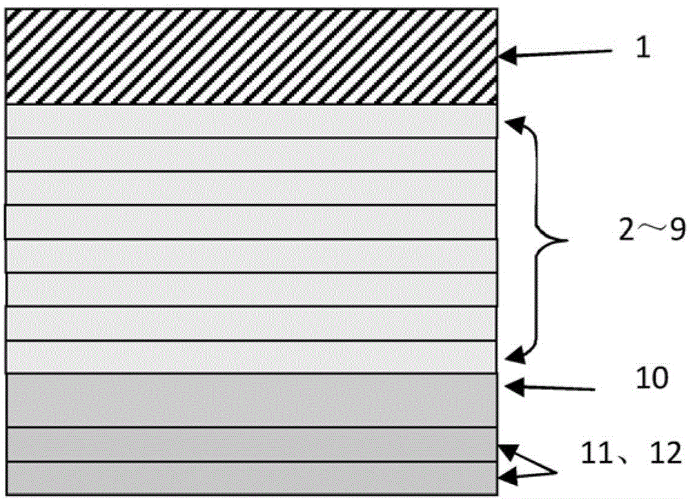
[0041] Embodiment 1 is used for the test of a plurality of samples of the same kind produced in the same batch. The growth parameters of each sample are close and the structure is the same.

[0042] figure 1A structural diagram of a sample according to an exemplary embodiment is shown. The sample includes a single crystal substrate 1, transition layers 2-9 grown sequentially on the single crystal substrate 1, a large mismatch material (with a large difference in lattice constant from the substrate) 10 grown on the transition layer 9, and Two layers of lattice fully strained material 11 and 12 grown on large mismatch material 10 .

[0043] The single crystal substrate 1 is a 4-inch GaAs single wafer, the direction of the crystal plane (100) and the monotectic plane (111) are 7 degrees, and the orientation side is the crystal plane Eight layers of InGaAlAs transition layers 2-9 are grown on the substrate 1 by means of MOCVD (Metal Organic Vapor Phase Chemical Deposition). T...

Embodiment 2

[0092] The sample structure of Example 2 is similar to that of Example 1. The test method of embodiment 2 is basically the same as that of embodiment 1, the difference is that it uses a rough RSM scan and a 1:n ω-2θ scan to test the sample for the same sample, and it is applied to different growth parameters. Sample-by-sample testing. The specific test process is as follows:

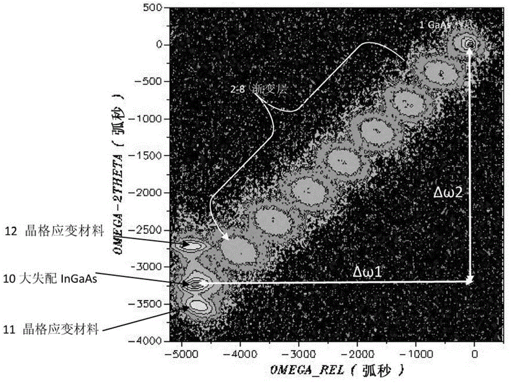
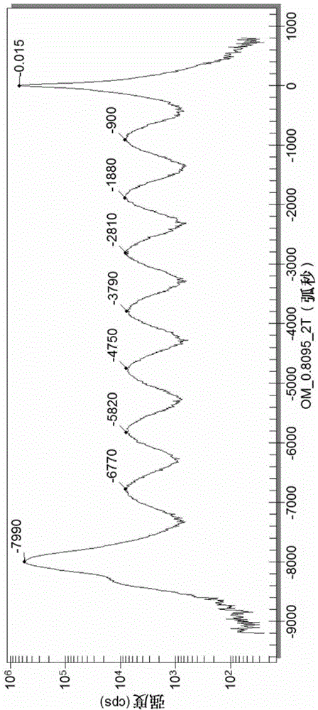
[0093] 1. For the sample to be tested, first roughly scan the RSM diagram of the (004) isosymmetric plane with a large step length (150 arc seconds), and the scanning interval is the same as in Example 1, that is, the ω_rel coordinate axis: -5200~500 arc seconds, ω-2θ coordinate axis: -4000~500 arc seconds. Then the (004) symmetry plane scan takes about 25 minutes. According to the RSM diagram obtained by rough scanning, the motion relationship 1:n of ω and 2θ was calculated in the same manner as in Example 1.

[0094] According to this embodiment, the range of the step size of the coarse scan can be...


PUM


Abstract

Disclosed is a method for testing a crystal by X-ray diffraction. The crystal comprises a single crystal substrate and at least one layer of lattice mismatch materials growing on the single crystal substrate. The method includes firstly, scanning a reciprocal space mapping of a sample, and calculating a motion speed ratio between a Omega-axial and a 2Theta-axial to be 1:n according to the reciprocal space mapping; and secondly, scanning the sample to be tested at the speed ratio of 1:n of the Omega-axial and the 2Theta-axial in a linking manner, and calculating interplanar spacing of the at least one layer of lattice mismatch materials according to an acquired scanning curve. By the method compared with the RSM (response surface methodology), lattice coefficient of the lattice mismatch materials can be quickly measured, speed can be increased by 20 times and precision in measurement is close to that in the RSM .

Description

technical field [0001] The invention relates to a method for testing crystals by using X-ray diffraction (XRD), in particular to a method for testing crystal lattice mismatch materials grown on a single crystal substrate by using X-ray diffraction (XRD). Background technique [0002] X-ray diffraction is a commonly used method for analyzing and testing crystals. By analyzing the X-ray diffraction patterns of crystals, information such as lattice constants, components, thickness, strain, stress, and relaxation of crystals can be obtained. [0003] Two scanning modes are known for X-ray diffraction testing of crystals. One is the ω-2θ scanning method, wherein the ω axis and the 2θ axis are linked at a speed ratio of 1:2, the ω axis corresponds to the direction of the X-ray incident, and the 2θ axis corresponds to the direction of the diffraction line. The ω-2θ curve is obtained by ω-2θ scanning for sample analysis. Another scanning method is Reciprocal Space Maps (RSM) scann...

Claims


Application Information

Patent Timeline
Patent Type & Authority Applications(China)
IPC IPC(8): G01N23/20
Inventor 吴志猛孙超魏郝然王伟明宋红
Owner DR TECH CO LTD YIXING JIANGSU
Why Eureka
Try Eureka