Method for compensating precision milling deformation of thin-wall blade

A deformation compensation and milling processing technology, which is applied in special data processing applications, instruments, electrical digital data processing, etc., can solve the problems of large deformation and difficult precision guarantee of thin-walled blades, and achieve improved surface contour and processing accuracy , the effect of reducing workload

Inactive Publication Date: 2013-01-16
NORTHWESTERN POLYTECHNICAL UNIV
View PDF3 Cites 42 Cited by
  • Summary
  • Abstract
  • Description
  • Claims
  • Application Information

AI Technical Summary

Problems solved by technology

[0007] In order to solve the problems in the prior art that the processing deformation of thin-walled blades is large and the accuracy is difficult to guarantee, the present invention proposes a thin-walled blade precision milling deformation compensa

Method used


Image

  • Method for compensating precision milling deformation of thin-wall blade
  • Method for compensating precision milling deformation of thin-wall blade
  • Method for compensating precision milling deformation of thin-wall blade

Examples


Embodiment Construction

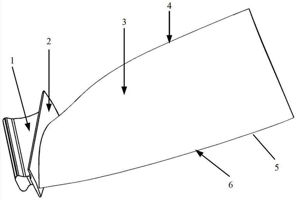
[0033] Describe the present invention below in conjunction with specific embodiment:

[0034] In this embodiment, the attached figure 2 Take the thin-walled blade of an aeroengine as an example, figure 2 The blade size shown is about: 303mm×115mm×1.8mm, the blade material is aerospace titanium alloy TC4; the cutter diameter is a ball-end cutter with a diameter of 10mm. The blade is processed by JOHNFORD VM850C four-axis CNC machining center. The axial direction of the blade coincides with the X-axis of the machine tool and can rotate 360° around the X-axis. The measuring equipment is a three-coordinate measuring machine GLOBAL STATUS 121510, and the probe radius is 1mm.

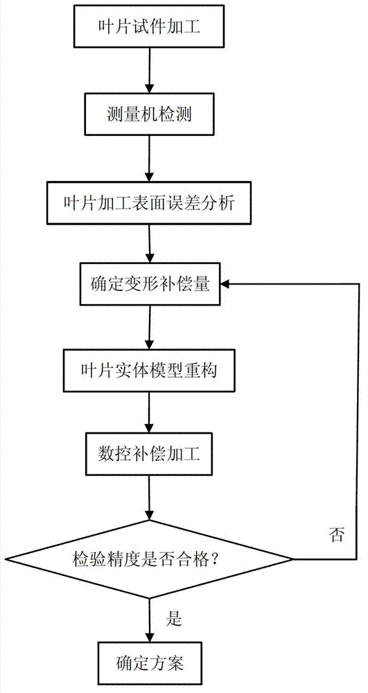
[0035] The specific compensation method steps are as follows:

[0036] Step 1: Extract 8 blade sections perpendicular to the parameter v direction in the 3D model of the blade, and extract the section lines of each blade section. The method of obtaining compensation for each section line is the same; the...


PUM


Abstract

The invention provides a method for compensating precision milling deformation of a thin-wall blade. The method includes extracting blade sections perpendicular to a parameter v-direction; measuring error mean values of the various sections after the blade is machined according to an initial three-dimensional model and using the error mean values as primary compensation quantities for the sections; reconstructing a three-dimensional blade model after the various sections are primarily compensated; machining the blade according to the reconstructed three-dimensional blade model; measuring maximum error values of the various sections; computing precise deformation compensation quantities for the various sections; secondarily reconstructing a three-dimensional blade model after the various sections are compensated according to the precise deformation compensation quantities; machining the blade according to the secondarily reconstructed three-dimensional blade model; and measuring errors of the various sections to judge whether design requirements are met or not. The method is favorable for improving the machining precision of the blade and the profile tolerance of the surface of the blade and reducing compensation frequency, machining frequency and workload of follow-up working procedures.

Description

technical field [0001] The invention belongs to the technical field of precision and ultra-precision cutting, and specifically relates to a thin-wall blade precision milling deformation compensation method, which mainly solves the deformation control problem of aero-engine thin-wall blade CNC milling finishing deformation control. Background technique [0002] The blade is the core part of the aero-engine, and it is also a typical thin-walled part. Its manufacturing level directly affects the aerodynamic performance of the aero-engine. With the continuous development of aerodynamic design technology, structure technology and material technology, aeroengine blades have new structural features such as bending, twisting, thinning, sweeping, and lightness, and at the same time, higher requirements are put forward for their manufacturing precision. The high-quality precision machining technology of aero-engine blades is a challenging topic in the manufacture of engine blades, and...

Claims


Application Information

Patent Timeline
IPC IPC(8): G06F17/50
Inventor 刘维伟单晨伟成宏军李晓燕蔡元元
Owner NORTHWESTERN POLYTECHNICAL UNIV
Why Eureka
Try Eureka