Control method for neutral-point voltage of bus of 10kW three-phase grid-connected inverter

A control method and a technology of a three-level inverter, which are applied in directions such as converting irreversible DC power input into AC power output, can solve the problems of uneven bus voltage division, increased power consumption, and low control accuracy, and achieve The effect of high power output quality requirements, reduced power loss, and simple control steps

Inactive Publication Date: 2013-01-16
JIANGSU KAIFAN ELECTRICAL APPLIANCES
View PDF4 Cites 12 Cited by
  • Summary
  • Abstract
  • Description
  • Claims
  • Application Information

AI Technical Summary

Problems solved by technology

However, due to the existence of problems such as capacitor production process, it is difficult to guarantee C 1 and C 2 are exactly the same, which in turn leads to the problem of uneven voltage division of the busbar, resulting in when N e When used as the zero point of the three-phase voltage, the output voltage of the T-type three-level inverter is not completely symmetrical in three phases, that is, the midpoint voltage fluctuation of the inverter occurs, which affects the power output quality
In the past, the control method for the voltage imbalance at the midpoint of the bus mostly used the method of voltage dividing resistors, the control accuracy was not high, and excessive energy consumption was generated on the resistors, which increased power consumption.

Method used


Image

  • Control method for neutral-point voltage of bus of 10kW three-phase grid-connected inverter

Examples


Embodiment Construction

[0008] Embodiments of the inventive method are as follows:

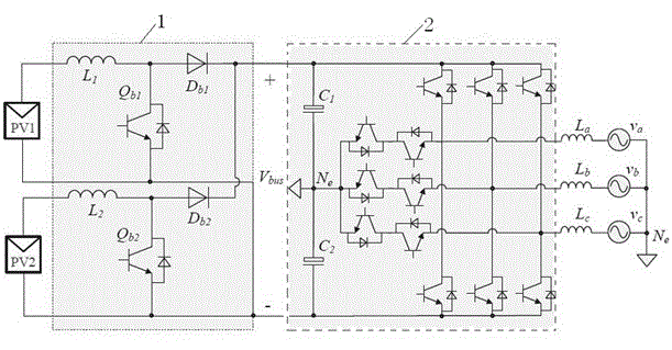
[0009] The method is based on figure 1 The main circuit of the 10kW inverter is shown. The front stage of this circuit adopts two-way Boost converter 1, L 1 and L 2 is the boost inductor, Q b1 and Q b2 is the main switching tube, D b1 and D b2 It is a freewheeling diode; the latter stage adopts a T-type three-level inverter 2, C 1 and C 2 is the bus voltage divider capacitor, L a , L b and L c is the inverter output filter inductance, v a , v b and v c is the three-phase voltage. In this embodiment, the input voltage of the photovoltaic panel is 250V-800V, the output voltage of the Boost converter is 800V, the output voltage of the inverter is 220V AC, and the bus voltage dividing capacitor C 1 and C 2 Both are 560μF. During the control process, the bus voltage dividing capacitor C is alternately used at intervals of 0.2 seconds 1 and C 2 The voltage at both ends is sampled to obtain the sampled va...


PUM


Abstract

The invention relates to a control technique of a photovoltaic power generation system device and particularly relates to a control method for a neutral-point voltage of a bus of a 10kW three-phase grid-connected inverter. The method comprises the following steps of: alternately sampling voltages at two ends of voltage dividing capacitor C1 and C2 of the bus at the same interval T to respectively obtain sampling values VC1 and VC2; and comparing VC1 and VC2 with 1/2 of the voltage value of the bus, if the deviation range exceeds a set value, regulating the duty ratio of main switch tubes in two Boost converters to ensure that the values of VC1 and VC2 are returned to be equal to the 1/2 of the voltage value of the bus. The method provided by the invention is simple in control step, a voltage dividing resistor is not required to be arranged, and the power consumption is reduced; and the whole process is controlled by virtue of computer software, so that the control precision is high, the stability of the neutral-point voltage of the bus is good, and therefore, the higher power output quality requirement can be fulfilled.

Description

technical field [0001] The invention relates to the control technology of photovoltaic power generation system equipment, in particular to a control method for the midpoint voltage of a busbar of a 10kW three-phase grid-connected inverter. Background technique [0002] In the existing photovoltaic power generation system, the topology of the main circuit of the inverter is as follows: figure 1 As shown, it usually includes a Boost converter located in the front stage of the front stage and a T-type three-level inverter located in the rear stage. The T-type three-level inverter includes a bus voltage dividing capacitor between the input bus bars C 1 and C 2 . Theoretically, the bus voltage dividing capacitor C 1 and C 2 The voltage at both ends is equal to provide voltage for the subsequent circuit. However, due to the existence of problems such as capacitor production process, it is difficult to guarantee C 1 and C 2 are exactly the same, which in turn leads to the p...

Claims


Application Information

Patent Timeline
Patent Type & Authority Applications(China)
IPC IPC(8): H02M7/48
Inventor 王颢雄周峰许跃宏牛孝如
Owner JIANGSU KAIFAN ELECTRICAL APPLIANCES
Why Eureka
Try Eureka