
Protective energy-saving pressure cooker

A pressure cooker and pot cover technology, applied in the field of pressure cooker, can solve the problems of large exposed area of ​​metal surface, easy to be scalded or scalded, and much heat lost, so as to speed up the cooking process and reduce the chance of scalding or scalding. Good insulation effect

Inactive Publication Date: 2013-01-23
黄昊 +2
View PDF0 Cites 23 Cited by
  • Summary
  • Abstract
  • Description
  • Claims
  • Application Information

AI Technical Summary

Problems solved by technology

However, the metal surface of ordinary pressure cooker has a large exposed area, especially the pot lid of pressure cooker, except that a small part is covered by the handle of the pot cover, most of the metal surface is exposed. During the cooking process, the exposed pot cover surface is in a relatively high temperature state , and because of its high surface temperature, when the human body accidentally touches it, it is easy to be scalded or scalded; the more obvious disadvantage is that during the cooking process of the pressure cooker, no matter whether the gas stove or the induction cooker is used, the pot of the high-temperature pressure cooker The cover is always in a state of radiating heat outward, and because of its high surface temperature, large exposed area, and a lot of heat loss, especially in winter when the ambient temperature is low, the temperature difference between the pot cover and the surrounding environment is large, and the heat dissipation is faster. More heat, which is not conducive to energy saving when cooking in a pressure cooker, nor is it conducive to heat preservation after cooking in a pressure cooker

Method used


Image

  • Protective energy-saving pressure cooker
  • Protective energy-saving pressure cooker
  • Protective energy-saving pressure cooker

Examples


Embodiment

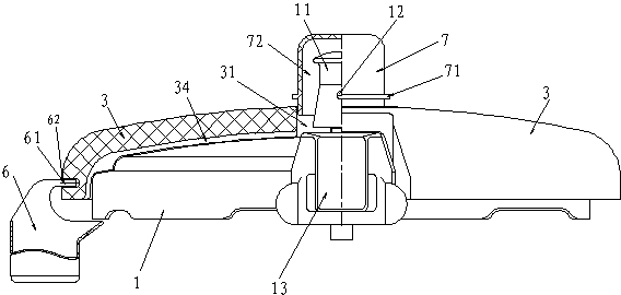
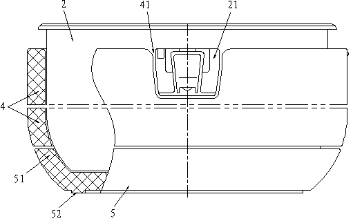
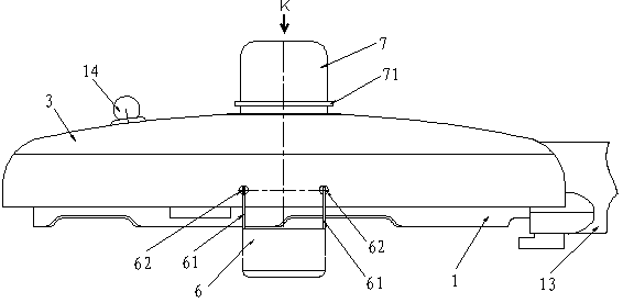
[0021] The protective energy-saving pressure cooker of the embodiment of the present invention (for the structure see Figure 1-Figure 8 ), including a pot body 2 and a matching pot cover 1, its structural feature is that: the pot cover 1 is also provided with a heat shield 3 covering its surface;

[0022] The above-mentioned heat shield 3 is an integral structure made of foamed plastic material; the heat shield 3 is provided with a valve position hole 31 for avoiding the bonnet 11 of the pressure limiting valve, and the circumference of the valve position hole 31 and the bonnet 11 There is a suitable exhaust space between the sides, so that the gas ejected from the valve cap 11 can be discharged from the space; the heat shield 3 is provided with a handle groove 32 for avoiding the cover handle 13 .

[0023] The above-mentioned heat shield 3 is provided with a safety hole 33 for avoiding the safety valve 14, so that the function of the safety valve 14 will not be affected.

...


PUM


Abstract

The invention provides a protective energy-saving pressure cooker, which comprises a cooker body and a cooker cover matched with the cooker body, wherein the cooker cover is further provided with a heat insulating cover; the heat insulating cover is made of a foamed plastic material, and is provided with a valve position hole; a steam exhaust gap is formed between the valve position hole and a valve cap; the heat insulating cover is provided with a handle avoiding groove and a safety hole; the inner side of the heat insulating cover is further provided with a diversion groove extending from the bottom end part of the valve position hole to the outer lower edge of the cooker cover along the outer surface of the cooker cover; the cooker body is provided with a heat insulating cylinder made of a foamed plastic material; and the lower part of the heat insulating cylinder is provided with a sleeve gasket which is made of a foamed plastic material and is sleeved at the bottom of the high pressure cooker. Due to the adoption of the pressure cooker, the defects existing in the conventional heat insulating technology are overcome, more ideal protecting, energy-saving and heat-preserving effects are achieved, and energy conservation and emission reduction are facilitated; and the protective energy-saving pressure cooker has popularization and application values.

Description

technical field [0001] The invention relates to a pressure cooker, in particular to a protective and energy-saving pressure cooker. Background technique [0002] Most of the cooking pressure cookers used by the public on gas stoves or induction cookers (hereinafter referred to as: pressure cookers or ordinary pressure cookers) are mostly made of aluminum alloy or stainless steel, which brings many conveniences to people's lives. Compared with automatic electric pressure cookers, ordinary pressure cookers In the cooking process, the firepower can be adjusted at any time at will, which has certain advantages in use. However, the metal surface of ordinary pressure cooker has a large exposed area, especially the pot lid of the pressure cooker. Except for a small part covered by the handle of the pot cover, the metal surface is mostly exposed. During the cooking process, the exposed pot cover surface is in a relatively high temperature state. , and because of its high surface te...

Claims


Application Information

Patent Timeline
IPC IPC(8): A47J27/08A47J36/36
Inventor 黄昊戴梦云戴永锋
Owner 黄昊
Learn More