Cyclone separation device

The technology of a cyclone separation device and a cyclone cylinder is applied in the direction of a cyclone device, a device whose axial direction of the cyclone can be reversed, etc. It can improve the separation efficiency, reduce the influence of the swirling flow velocity, and improve the efficiency.

Inactive Publication Date: 2013-01-23
TWINBIRD CORP
View PDF8 Cites 2 Cited by
  • Summary
  • Abstract
  • Description
  • Claims
  • Application Information

AI Technical Summary

Problems solved by technology

That is, such a cyclone separation device has the problem that the number of rotations of the swirling flow in the above-mentioned conical cylinder is small.
Therefore, there is a possibility that the centrifugal force cannot sufficiently act on the suspended matter, and the fluid in the state where the suspended matter remains passes through the cyclone separator.
Although it is also considered to reduce the difference in radius between one end and the other end of the above-mentioned conical cylinder, in this case, the flow velocity of the swirling flow does not increase, so the centrifugal force acting on the suspended matter does not increase, so there is no way to improve the suspension. The problem of the efficiency of material separation from swirling flow

Method used


Image

  • Cyclone separation device
  • Cyclone separation device
  • Cyclone separation device

Examples


Embodiment Construction

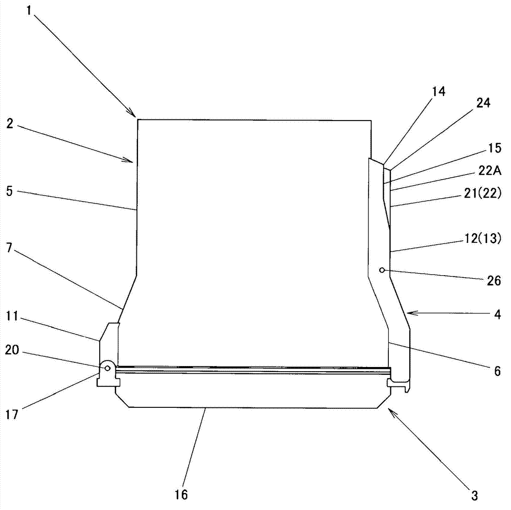
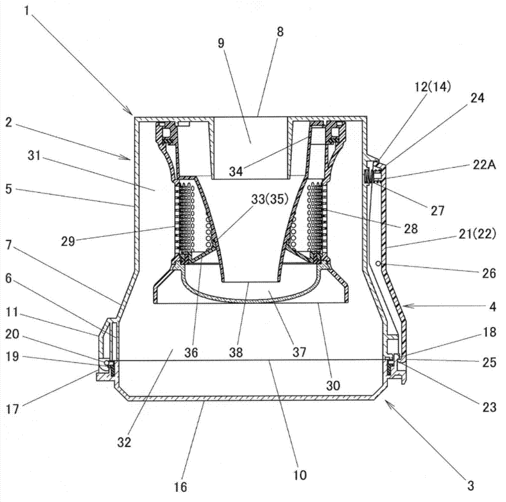
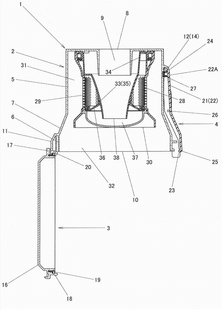
[0016] Below, according to Figure 1 to Figure 4 Embodiments of the present invention will be described. Also, in the following description, the Figure 1 to Figure 4 Up and down in is specified as up and down. and, will Figure 1 to Figure 4 The left in the middle is defined as the front, and the right is defined as the rear. Reference numeral 1 denotes a cyclone dust collector as a cyclone separation device of the present invention. The cyclone dust collector 1 has a cyclone 2 , a bottom cover 3 , and an engaging mechanism 4 .

[0017] The cyclone 2 is formed of transparent synthetic resin. Furthermore, the cyclone 2 has a small-diameter portion 5 with a relatively small diameter, a large-diameter portion 6 with a relatively large diameter, and an intermediate portion 7 whose diameter gradually changes so as to connect the small-diameter portion 5 and the large-diameter portion 6 . An exhaust port 8 connected to an electric blower (not shown) is formed at the upper end...


PUM


Abstract

The invention provides a cyclone separation device which can improve the efficiency of separating suspended matter in a fluid. In a cyclone type dust collection device, as a cyclone separation device, which has a hollow and substantially tapered second cyclone cylinder, an accelerating area at an upstream side and a centrifugal force amplifying area at a downstream side are arranged in a central axis (X) direction and constitute the abovementioned cyclone cylinder, in the abovementioned accelerating area, the circulation area (Ab) decrease from a start end of the central axis (X) direction to a finish end, and in the abovementioned centrifugal force amplifying area, the circulation area (Ac) decreases from the start end of the central axis (C) direction to the finish end, thus, after the flow velocity of rotating flow rises in the accelerating area, in the centrifugal force amplifying area, the increase of the rate of rise of the velocity of the rotating flow can be inhibited and the velocity (Vc) is enabled to rise, and the rotating times of the rotating flow at a relatively fast flow velocity (Vc) increases, improving the efficiency of separation of suspended matter, i.e. dust, in the rotating flow.

Description

technical field [0001] The invention relates to a cyclone separation device. Background technique [0002] In the past, as this kind of cyclone separation device, the following technology is known: the air flow is made to flow along the inner wall of the conical cylinder (corresponding to the cyclone of the present invention) to form a swirling flow, and the powder contained in the swirling flow is Centrifugation is performed (for example, refer to Patent Document 1.). The cyclone separation device is configured such that the radius of the conical cylinder decreases proportionally from one axial end toward the other end. [0003] Patent Document 1: Japanese Patent Application Publication No. 6-77661 [0004] However, in such a cyclone separator, the flow velocity of the swirling flow is accelerated in the vicinity of the outlet of the conical cylinder. This is because the relationship between the flow rate Q of the airflow, the flow velocity V, the cross-sectional area A ...

Claims


Application Information

Patent Timeline
Patent Type & Authority Applications(China)
IPC IPC(8): B04C5/081
Inventor 松尾和则
Owner TWINBIRD CORP
Why Eureka
Try Eureka