
Fuel oil atomizing device

A technology of fuel atomization and fuel oil, applied in the direction of combustion chamber, combustion method, combustion type, etc., can solve the problems of unable to meet the requirements of stable and efficient combustion of the combustion chamber, short range of oil mist, high axial jet velocity, etc., to achieve increased The effect of centrifugal atomization, increasing the average area, and ensuring reliability

Inactive Publication Date: 2013-01-23
HARBIN DONGAN ENGINE GRP
View PDF3 Cites 5 Cited by
  • Summary
  • Abstract
  • Description
  • Claims
  • Application Information

AI Technical Summary

Problems solved by technology

The gas passing through the evaporating tube atomizing nozzle is a high-temperature oil-gas mixture, which is easier to mix and burn with the air in the main combustion area, providing good conditions for efficient and stable combustion; T-shaped evaporating tubes and Г-shaped evaporating tubes are commonly used at present , are single tubular structure, the spray shape is a single straight-line conical structure, the axial jet velocity is high, and for some aero-engines, the flame tube structure is compact, the head space is small, and the oil mist will be sprayed to the wall of the flame tube ; and due to the large fuel flow in the combustion chamber, the atomization effect of the conventional evaporator tube will decrease
Therefore, there is a need for an atomizing nozzle with good atomization effect and short oil mist range. The conventional evaporation tube cannot meet the stable and efficient combustion requirements of this combustion chamber.

Method used


Image

  • Fuel oil atomizing device
  • Fuel oil atomizing device

Examples


Embodiment Construction

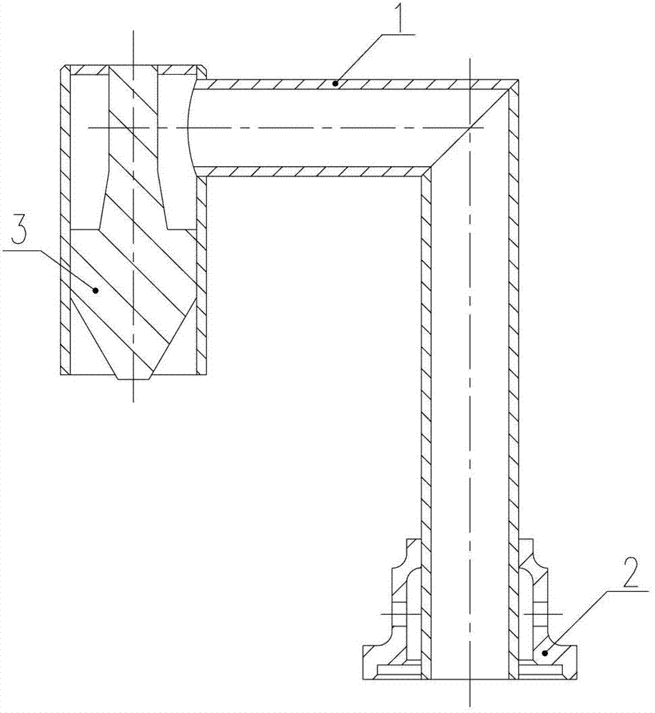
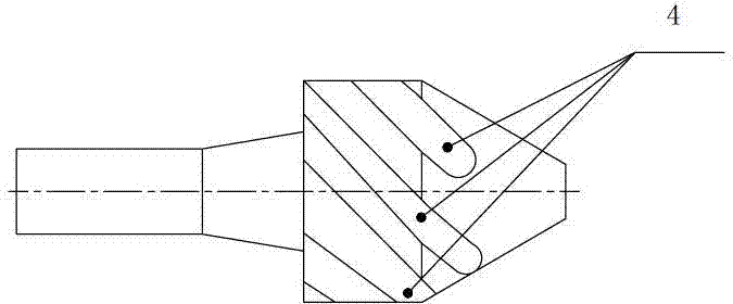
[0009] As shown in the figure, the fuel atomization device includes an evaporating tube 1, an air cup 2 and an oil swirler 3. The evaporating tube 1 is a Γ-shaped three-section tube at 90° to each other. At the fuel outlet of the evaporating tube 1 An oil spinner 3 is provided inside the oil spinner 3, and the outer surface of the oil spinner 3 is provided with 4 to 6 spiral grooves 4, and an air cup 2 is installed outside the evaporation pipe 1 at the fuel inlet, and the air cup 2 The mouth of the cup is flush with the fuel inlet of the evaporating tube 1, and an air outlet is provided on the side wall of the air cup 2. The number of air outlets provided on the side wall of the air cup is 6, and the number of the spiral grooves is preferably 5. The installation method of the air cup and the evaporation tube is welding.


PUM


Abstract

The invention relates to a fuel oil atomizing device which comprises an evaporation pipe, an air cup and an oil rotating device, wherein the evaporation pipe is formed by three sections of reversed-L-shaped pipes which form angles of 90 degrees; the oil rotating device is arranged at the inner part of a fuel oil outlet of the evaporation pipe; 4-6 spiral grooves are arranged on the outer surface of the oil rotating device; the air cup is mounted at the outer part of the evaporation pipe at the fuel oil inlet; a cup opening of the air cup is leveled with the fuel oil inlet of the evaporation pipe; and an air outlet is arranged on the side wall of the air cup. The fuel oil atomizing device disclosed by the invention realizes the aim of sufficiently atomizing under the condition of a very short oil mist range so that the evaporation rate is improved and good conditions are provided for stable and efficient combustion.

Description

technical field [0001] The invention relates to an atomizing device, in particular to a fuel atomizing device. Background technique [0002] The evaporating tube atomizing device is one of the fuel atomizing nozzles. It is used in both large and small combustion chambers. It is generally installed at the head of the flame tube in the main combustion chamber of the engine. The main functions are: the high-temperature gas in the main combustion area passes through the evaporation The tube wall faces the heating of the fuel in the evaporating tube, and the high-temperature, high-speed inlet air impacts and heats the fuel in the evaporating tube to achieve the effect of evaporating and atomizing the fuel. The gas passing through the evaporating tube atomizing nozzle is a high-temperature oil-gas mixture, which is easier to mix and burn with the air in the main combustion area, providing good conditions for efficient and stable combustion; T-shaped evaporating tubes and Г-shaped ...

Claims


Application Information

Patent Timeline
Patent Type & Authority Applications(China)
IPC IPC(8): F23R3/32F23D11/44
Inventor 姜山李洪伏王忠鹏江红兵
Owner HARBIN DONGAN ENGINE GRP
Learn More