Tri-band integrated antenna

An antenna and helix technology, applied in the field of three-frequency integrated antenna, can solve the problems of large influence on antenna performance, poor phase center stability, narrow frequency band coverage bandwidth, etc., and achieve easy independent debugging, compact antenna structure and optimal performance Effect

Active Publication Date: 2013-01-23
SPACE STAR TECH CO LTD
View PDF8 Cites 13 Cited by
  • Summary
  • Abstract
  • Description
  • Claims
  • Application Information

AI Technical Summary

Problems solved by technology

[0003] However, the current tri-band or multi-band antenna generally adopts a microstrip stacked antenna based on dielectric loading, such as the patent "a tri-band circularly polarized stacked microstrip antenna" (application number: CN201020274629.2), and the patent "a The Design of Three-band Dual Circular Polarization GPS Microstrip Patch Antenna" (application number: CN200710099068.X), this type of antenna reduces the volume and cost of the antenna while meeting the requirements of multi-band work, but this type of antenna The radiation efficiency is low, the mutual coupling between each frequency point is serious, and debugging is difficult. At the same time, due to the direct feeding of the probe, the coverage bandwidth of each frequency band is narrow, and the stability of the phase center is poor.
The patent "Planar Tri-Band Antenna" (Application No.: CN200620068895.3) and the patent "New Tri-Band Planar Inverted-F Antenna" (Application No.: CN200910199589.1) adopt the form of planar microstrip slotting and adding parasitic units. It can also couple multiple frequencies, but this type of antenna can only radiate linearly polarized electromagnetic waves, and it occupies a large installation area in the UHF frequency band
At the same time, the above-mentioned three-band or multi-band antenna generally uses microwave dielectric material as the substrate, and its dielectric constant has a great influence on the performance of the antenna, and in the environment of alternating cold and heat in the space, there may be problems between the metal clad copper and the microwave dielectric board. Phenomena such as warping and falling off, the reliability is low, and it is not suitable as a spaceborne antenna

Method used


Image

  • Tri-band integrated antenna
  • Tri-band integrated antenna
  • Tri-band integrated antenna

Examples


Embodiment Construction

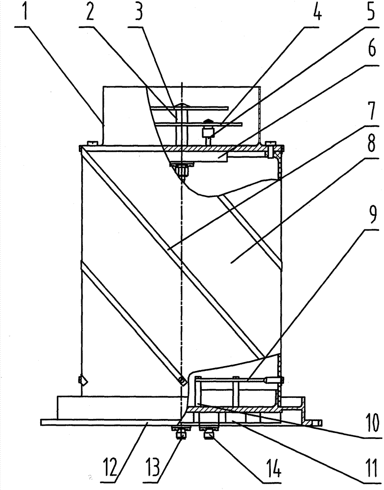
[0028] The antenna of the invention has the characteristics of high phase center stability, multi-band coverage, small size, light weight, and circular polarization, and is suitable for multi-frequency satellite-borne high-precision measurement systems, and can also be used as an airborne antenna.

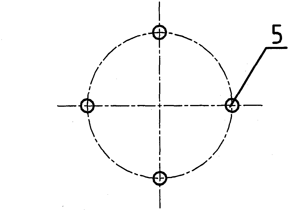
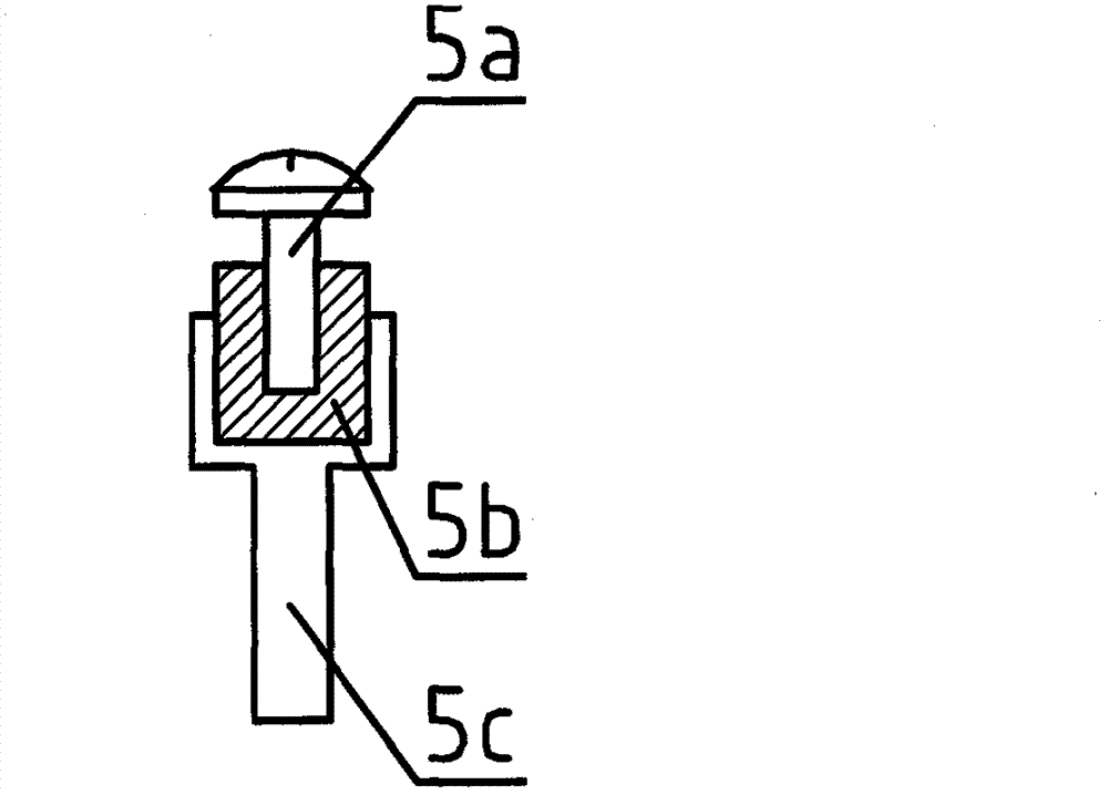
[0029] Such as figure 1 As shown, the tri-frequency integrated antenna of the present invention includes a reflection cavity 1, a metal support column 2, a radiation upper patch 3, a radiation lower patch 4, a plurality of metal sleeve feeding probes 5, and L\S feeding Network 6, multiple helical wires 7, support sleeve 8, feed connection part 9, UHF feed network 11, antenna base 12, L\S electrical connector 13 and UHF electrical connector 14. The reflective cavity 1 is a metal hollow cylinder with a closed bottom, and the reflective cavity 1 can also be a circular bowl-shaped structure. The metal support column 2 is installed at the center of the inner cavity bottom of the reflec...


PUM


Abstract

The invention discloses a tri-band integrated antenna. The antenna consists of two parts, namely an L / S radiating unit and an ultra-high frequency (UHF) radiating unit, wherein the L / S radiating unit comprises a plurality of metal sleeve feed probes, an L / S feed network, an upper radiating piece, a lower radiating piece and a reflection chamber; the UHF radiating unit comprises a plurality of spiral lines, a supporting sleeve, a feed connecting part, an UHF feed network and a base; the spiral lines are wound on the supporting sleeve; the bottom ends of the spiral lines are connected with the output port of the UHF feed network through the feed connecting part; and the UHF feed network is arranged in the base. The antenna provided by the invention has high phase centre stability, a compact structure and a small size, and can cover UHF, an L-band and an S-band, and meet the requirements of spaceborne or airborne.

Description

technical field [0001] The invention relates to an antenna, in particular to a three-frequency integrated antenna. Background technique [0002] With the development of pan-star measurement technology, it is required that the antenna can work in a wide frequency band or even in multiple frequency bands to receive or transmit signals in different frequency bands. At the same time, within a limited aperture, the size and weight of the antenna are usually compared. Strict requirements, and in order to ensure measurement accuracy, the antenna is also required to have a high phase center stability. Therefore, high-performance, compact tri-band or multi-band antenna technology has become an urgent problem to be solved. [0003] However, the current tri-band or multi-band antenna generally adopts a microstrip stacked antenna based on dielectric loading, such as the patent "a tri-band circularly polarized stacked microstrip antenna" (application number: CN201020274629.2), and the p...

Claims


Application Information

Patent Timeline
IPC IPC(8): H01Q19/17H01Q21/30H01Q1/50H01Q1/36
Inventor 柯炳清王昕尹建勇李时良李景贵
Owner SPACE STAR TECH CO LTD
Why Eureka
Try Eureka