
Improved dead-beat control method for pulse width modulation (PWM) rectifier at unbalance of voltage of power grid

A technology of deadbeat control and grid voltage, which is applied to the control of voltage-type PWM rectifiers and the field of improved deadbeat control of PWM rectifiers when the grid voltage is unbalanced. Stability and other issues, to achieve the effect of easy implementation, suppression of power pulsation, and safe operation

Inactive Publication Date: 2013-01-23
HENAN NORMAL UNIV
View PDF4 Cites 20 Cited by
  • Summary
  • Abstract
  • Description
  • Claims
  • Application Information

AI Technical Summary

Problems solved by technology

Under the unbalanced condition of the power grid, the input and output power of the three-phase voltage-type PWM rectifier based on the traditional deadbeat control method will be unstable, the DC bus voltage will fluctuate, and the power electronic equipment will flow a large negative sequence current, which will affect the power. Safe operation of devices and quality control of rectifiers

Method used


Image

  • Improved dead-beat control method for pulse width modulation (PWM) rectifier at unbalance of voltage of power grid
  • Improved dead-beat control method for pulse width modulation (PWM) rectifier at unbalance of voltage of power grid
  • Improved dead-beat control method for pulse width modulation (PWM) rectifier at unbalance of voltage of power grid

Examples


Embodiment Construction

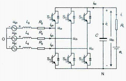
[0012] The present invention will be further described below in conjunction with the accompanying drawings. The topology of the main circuit of the three-phase voltage-type PWM rectifier is as follows: figure 1 shown. In the figure, u ga , u gb , u gc is a three-phase voltage source on the AC side, i ga , i gb , i gc is the input current of the three-phase AC side, u ca , u cb , u cc is the three-phase voltage at the input side of the power bridge, u dc is the DC side voltage, L g and R g are the incoming inductance and its equivalent resistance, respectively, C is the DC filter capacitor, O is the midpoint of the grid, i L is the load current, the DC side load is determined by the resistor R L equivalent representation.

[0013] Under the condition that the three-phase voltage of the power grid is balanced and stable, the mathematical model of the PWM rectifier in the synchronous rotating coordinate system can be obtained:

[0014] ...


PUM


Abstract

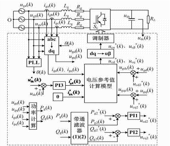
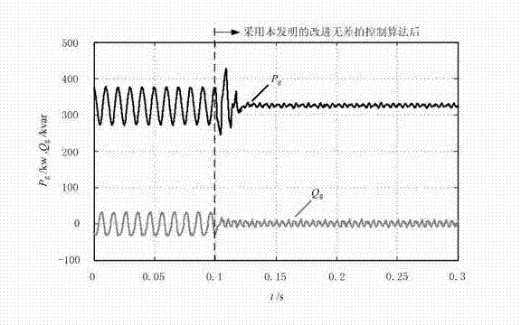
The invention discloses an improved dead-beat control method for a pulse width modulation (PWM) rectifier at unbalance of voltage of a power grid. According to the technical scheme, the key point is that the improved dead-beat control method for the PWM rectifier at unbalance of voltage of the power grid comprises the following steps of: respectively obtaining an active power double-frequency voltage compensation item and a reactive power double-frequency voltage compensation item by a bandpass filter and a proportion and integration (PI) controller through compensation voltage calculation according to input active power and input reactive power; obtaining a reference value of input voltage of the converter by taking the voltage compensation items as inputs of a built voltage reference value calculation model; performing reversed Park conversion by taking the voltage position angle of the power grid as a conversion angle to obtain input voltage under a two-phase static coordinate system; and generating a switching signal for controlling a power device by performing space vector pulse width modulation on the voltage signal. By the method, the model of the PWM rectifier can be compensated in real time, the pulses of the input active power and the input reactive power of the PWM rectifier can be effectively suppressed, and the voltage fluctuation of a direct current bus can be reduced.

Description

technical field [0001] The invention relates to a control method of a voltage-type PWM rectifier, which belongs to the control field of power electronic power conversion devices, in particular to an improved deadbeat control method of a PWM rectifier when the grid voltage is unbalanced. Background technique [0002] For the operation and control of power converters, scholars in related fields have proposed many advanced control algorithms, such as single-cycle control, predictive current control, adaptive control, sliding mode variable structure control and deadbeat control, etc., based on space voltage vector The PWM current deadbeat control method has constant switching frequency and good regulation performance, and its application in power electronics has shown great advantages. The deadbeat control method is based on the mathematical model of the control object, and calculates the control output in the current control cycle by sampling the feedback variable values, s...

Claims


Application Information

Patent Timeline
IPC IPC(8): H02M7/219H02M1/14
Inventor 王萌施艳艳
Owner HENAN NORMAL UNIV
Learn More