System and method for measuring frame delay time of photographing system of optical measurement device

A camera system and time measurement technology, applied in the field of photogrammetry, can solve problems such as delay calibration, error, camera delay change, etc., and achieve the effect of precise calibration, accurate calibration results, and accurate and reliable calibration results

Active Publication Date: 2013-01-23
INST OF OPTICS & ELECTRONICS - CHINESE ACAD OF SCI
View PDF3 Cites 31 Cited by
  • Summary
  • Abstract
  • Description
  • Claims
  • Application Information

AI Technical Summary

Problems solved by technology

To sum up, these factors make the image output by the camera after the exposure is not the image of the current frame, generally delayed by 0~3 frames; for some complex camera systems, this delay may be 10 frames or even more Big
Latency cannot be calibrated by static conditions
At the same time, because the delay of image output is related to the settings of the camera system, if the frame rate of the camera changes, the delay of the camera will also change.
Delay has no effect on the measurement of static targets by optical measurement equipment, but it will cause large errors in the measurement of dynamic targets

Method used


Image

  • System and method for measuring frame delay time of photographing system of optical measurement device
  • System and method for measuring frame delay time of photographing system of optical measurement device

Examples


Embodiment Construction

[0026] The present invention will be further described below in conjunction with the accompanying drawings and specific embodiments.

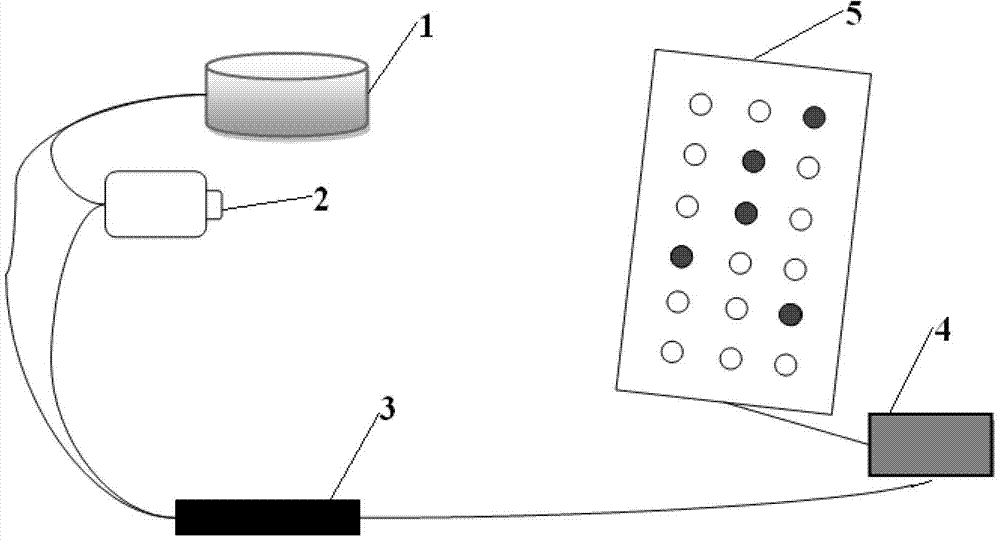
[0027] A system for measuring the frame delay time of an optical measurement equipment camera system, including a camera system 2, a time system terminal 3, an image recording device 1, a control and display LED light array device 4 and an LED light array 5, and the time system terminal 3 is connected to the recording device 1. The camera system 2 and the control and display LED lamp array device 4 , the output end of the camera system 2 is connected to the image recording device 1 , and the camera system 2 images the LED lamp array 5 .

[0028] In the system for measuring the frame delay time, the turn-on and turn-off time of the LED light is much shorter than one frame time, which is relatively negligible;

[0029] In the system for measuring frame delay time, the recording device can superimpose the collected time information into the digita...


PUM


Abstract

The invention discloses a system and a method for measuring frame delay time of a photographing system of an optical measurement device. The system comprises an image recording apparatus (1), a photographing system (2), a timing terminal (3), a control and display LED (Light-Emitting Diode) lamp array apparatus (4) and an LED lamp array (5). The method comprises the following steps of: judging the number of image outputting delay frames of a video camera, according to the time information on a digital image output by the photographing system and the information of the LED lamp array; providing time and external interruption signals by the timing terminal; recording the image of the photographing system and superposing the time information of the recording moment by the image recording apparatus; controlling an LED array to turn on or turn off the LED lamps by the control and display LED lamp array apparatus according to the external interruption signal and the time information; and imaging the LED array by the photographing system. The system and the method provided by the invention realize accurate calibration on image outputting delay time of the photographing system.

Description

technical field [0001] The invention relates to the calibration of high-precision optical measurement equipment, and the fields of photogrammetry and the like. Background technique [0002] Optical measurement equipment is a kind of non-contact measurement equipment. It images the target, and then obtains the position, attitude and other information of the target by processing the image. Due to the measurement accuracy of optical measuring equipment, optical measuring equipment has been widely used in various fields of civil and military use. In photometric equipment, the camera system is an important device, which consists of a camera, lens and other auxiliary circuit devices. In the production process of optical measurement equipment, in order to clearly understand the accuracy of the equipment, it is generally necessary to calibrate the camera system. The purpose of calibration is to determine the optical center, optical axis, focal length and some other physical parame...

Claims


Application Information

Patent Timeline
Patent Type & Authority Applications(China)
IPC IPC(8): H04N17/00G01C25/00
Inventor 张涯辉何培龙张桐杜俊峰张孟伟
Owner INST OF OPTICS & ELECTRONICS - CHINESE ACAD OF SCI
Why Eureka
Try Eureka