Lightning protection method and device for wind generating set
A technology for wind turbines and lightning currents, applied in wind turbine components, wind engines, wind power generation, etc., can solve problems affecting the safe operation of wind turbines, endangering the reliability of pitch bearings, and damage to pitch bearings, etc. Achieve flexible installation methods, good electrical conductivity, and low cost
- Summary
- Abstract
- Description
- Claims
- Application Information
AI Technical Summary
Problems solved by technology
Method used
Image
Examples
Embodiment 1
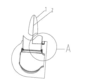
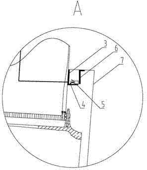
[0029] Such as figure 1 , figure 2 As shown, a down conductor 2 is laid in the blade 1, and the down conductor 2 in the blade 1 is laid inside the blade 1, and is connected to the carbon brush holder 3 on the surface of the blade 1 near the blade root, and the carbon brush holder 3 is used for fixing The carbon brush 5, the lead wire 4 of the carbon brush 5 is connected to the carbon brush bracket 3, and the carbon brush 5 is brushed to the conductive ring 6 fixed on the hub cover 7, so that the electrical connection between the blade 1 and the hub cover 7 is realized. When the current hits the blade air-termination device, the discharge path of the lightning current is the blade air-termination device--the down conductor--the carbon brush on the surface of the blade--the conductive ring on the hub cover, so that the lightning current is conducted to the hub cover Then the hubcap transmits the lightning current to the nacelle cover through the lightning device, and then to t...
Embodiment 2
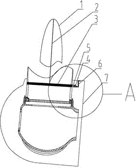
[0031] Such as image 3 , Figure 4 As shown, a downconductor 2 is laid in the blade 1, and the downconductor 2 in the blade 1 is laid inside the blade 1, and is connected to the conductive ring 6 on the surface of the blade near the blade root, and a carbon is fixed in the hubcap 7 The brush bracket 3 is used to install the carbon brush 5, the carbon brush 5 is connected to the conductive ring 6, and the carbon brush lead wire 4 connected to the carbon brush 5 is also fixed on the carbon brush bracket 3, and the carbon brush 5 is used to transition to connect the blade 1 and the hub cover 7, so as to realize the electrical connection between the rotating parts. When the lightning current hits the blade lightning receptor, the discharge path of the lightning current is the blade lightning receptor-down conductor-blade surface conductive ring- —Carbon brush——hub cover, so that the lightning current is conducted to the hub cover, and then the hub cover conducts the lightning cu...
Embodiment 3
[0033] Such as Figure 5 , Figure 6 As shown, the down conductor 2 is laid in the blade 1, and the down conductor 2 in the blade 1 is laid inside the blade 1. The difference between embodiment 3 and embodiment 1 is that in embodiment 3, the carbon brush holder 3 Installed in the vertical direction next to the blade root, the carbon brush lead wire 4 is connected to the down conductor 2, the conductive ring 6 is hooped on the side of the hubcap 7, and the carbon brush 5 is connected to the conductive ring 6. In this way, the electrical connection between the blade 1 and the hubcap 7 is realized. When the lightning current hits the blade lightning receptor, the discharge path of the lightning current is the blade lightning receptor—the down conductor—the carbon brush on the blade surface— —The conductive ring on the hubcap, so that the lightning current is conducted to the hubcap, and then the hubcap conducts the lightning current to the nacelle cover through the lightning dev...
PUM
 Abstract
Description
Claims
Application Information
 - R&D
- Intellectual Property
- Life Sciences
- Materials
- Tech Scout
- Unparalleled Data Quality
- Higher Quality Content
- 60% Fewer Hallucinations
Browse by: Latest US Patents, China's latest patents, Technical Efficacy Thesaurus, Application Domain, Technology Topic, Popular Technical Reports.
© 2025 PatSnap. All rights reserved.Legal|Privacy policy|Modern Slavery Act Transparency Statement|Sitemap|About US| Contact US: help@patsnap.com


