External displacement sensor

A displacement sensor and outer sleeve technology, applied in the direction of fluid pressure actuating devices, etc., can solve the problems of shortened sensor life, large downtime, and displacement sensor damage, achieve high detection accuracy and response frequency, and meet the needs of position control. , the effect of prolonging the service life

A displacement sensor and outer sleeve technology, applied in the direction of fluid pressure actuating devices, etc., can solve the problems of shortened sensor life, large downtime, and displacement sensor damage, achieve high detection accuracy and response frequency, and meet the needs of position control. , the effect of prolonging the service life

CN102900728AActive Publication Date: 2013-01-30CHINA NAT HEAVY MACHINERY RES INSTCO

Image

  • External displacement sensor
  • External displacement sensor

Examples


Embodiment 1

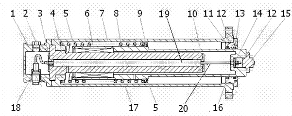
[0017] Embodiment 1 is a schematic diagram of the installation of a LVDT type linear displacement sensor.

[0018] Such as figure 1 As shown, a kind of external displacement sensor, comprises: linear bearing 6, outer sleeve 7, spring 8, slide guide rod 4, displacement sensor measuring rod 19 and moving sleeve 17, displacement sensor measuring rod 19 is in sliding guide rod 4 Inside, the sliding guide rod 4 is inside the outer sleeve 7, the sliding guide rod 4 and the outer sleeve 7 are coaxially fixed by screws, and there is an annular space for placing the linear bearing 6 between the moving sleeve 17 and the sliding guide rod 4, and the linear bearing 6 In the annular space; the spring 8 is fixed by the spring seat 9 in the inner hole of the outer sleeve 7, the retaining ring 5 is installed on the left end of the moving sleeve 17, the spring seat 9 is installed between the moving sleeve 17 and the outer sleeve 7, and the When the spring 8 is loaded into the moving sleeve 17...

Embodiment 2

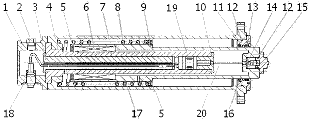
[0024] Embodiment 2 is a schematic diagram of the installation structure of the SONY MD50 series magnetic ruler and magnetic head.

[0025] figure 2 As shown, the difference from Embodiment 1 is that the shapes of the inner hole of the sliding guide rod 4, the fixed gland 3 on the outlet side and the flange gland 10 are different, which is only due to the different shapes of the detection heads of the two types of sensors.

[0026] The principle of the present invention is: by fixing the measuring rod (magnetic head) of the displacement sensor in the sliding guide rod, and the iron core (magnetic ruler) of the displacement sensor is installed in the moving sleeve through the flange type fixing assembly, the sensor position detection process The middle moving sleeve and the sliding guide rod produce concentric relative sliding along the axis, and an air communication hole is set on each of the moving sleeve and the sliding guide rod to ensure that the main body will not crawl ...


PUM


Abstract

The invention relates to an external displacement sensor. The external displacement sensor is characterized by comprising a linear bearing, an outer sleeve, springs, a sliding guide rod, a displacement sensor measuring rod and a movable sleeve, wherein the displacement sensor measuring rod is located in the sliding guide rod, the sliding guide rod is located in the outer sleeve, the sliding guide rod and the outer sleeve are coaxially fixed through screws, an annular space which is used for containing the linear bearing is formed between the movable sleeve and the sliding guide rod, and the linear bearing is located in the annular space; and the springs are fixed in an internal hole of the outer sleeve through spring seats, retaining rings are mounted at the left end of the movable sleeve, the spring seats are mounted between the movable sleeve and the outer sleeve, the movable sleeve is provided with a sealing cover at the end part of the outer sleeve, an O-shaped sealing ring is arranged between the sealing cover and the outer sleeve, and a dustproof ring and a combined seal are arranged between the sealing cover and the movable sleeve. The external displacement sensor has the advantages that the mounting and replacement are convenient, the sensing accuracy and operational reliability of the displacement sensor can be guaranteed, the contact wear to the sensor arising from uncoaxiality is avoided, and the service life is prolonged.

Description

technical field [0001] The invention belongs to the field of metallurgical equipment, in particular to an external displacement sensor used in a hydraulic servo oil cylinder. Background technique [0002] In the field of metallurgical equipment, hydraulic servo cylinders are widely used. In order to achieve position control, each set of servo hydraulic cylinders is usually equipped with a displacement sensor for open-loop or closed-loop control of the position of the controlled equipment. LVDT type linear displacement sensor and SONY MD50 series magnetic head are two types of displacement sensors commonly used in hydraulic servo cylinders of metallurgical equipment. The following problems often occur in the installation of these two types of sensors: [0003] For displacement sensors of the built-in installation type. If the eccentric load of the oil cylinder causes the piston to tilt during the working process, the sensor core (magnetic scale) will be bent and deformed, r...

Claims


Application Information

Patent Timeline
30 Jan 2013
Publication
CN102900728A
IPC
F15B15/28
Inventors
甄永富; 谢世明