
8-analogue-shaped soil uniaxial tensile tester

A uniaxial tensile tester technology, applied in the direction of applying stable tension/pressure to test the strength of materials, etc., can solve the problem that the tensile stress-strain curve cannot be measured, the loading process is affected by human factors, and the sample breaking point Large randomness of position and other problems, to achieve the effect of low cost, uniform force and reliable data

Inactive Publication Date: 2013-01-30
SUZHOU NANZEE SENSING TECH
View PDF5 Cites 29 Cited by
  • Summary
  • Abstract
  • Description
  • Claims
  • Application Information

AI Technical Summary

Problems solved by technology

[0005]Many current uniaxial tensile devices are improved on the basis of direct shear equipment, and are mainly stress-controlled, that is, by gradually increasing the weight The obvious disadvantage of loading control is that the complete tensile pressure-strain relationship curve of the soil cannot be measured, and the soil will be brittle when it reaches the tensile strength, which does not meet the characteristics of the soil as a plastic material.
The softening and deformation process of the soil after reaching the tensile strength is the key to studying its fracture mechanism and establishing a mathematical model of the fracture process. The above-mentioned stress-type tensile tester cannot measure the softening deformation data.
[0006] To sum up, the existing soil uniaxial tensile testers at home and abroad mainly have the following deficiencies: (1) During the tensile test, the sample is difficult to Fixed, cumbersome operation, large randomness of the sample breakpoint position; (2) Reshaping the soil sample preparation process will lead to artificial weakness and reduce the reliability of the test results;
[0007] (3) Using stress-controlled loading, the complete tensile stress-strain curve cannot be measured, the loading process is affected by human factors, and the accuracy of the test results is poor

Method used


Image

  • 8-analogue-shaped soil uniaxial tensile tester
  • 8-analogue-shaped soil uniaxial tensile tester
  • 8-analogue-shaped soil uniaxial tensile tester

Examples


Embodiment

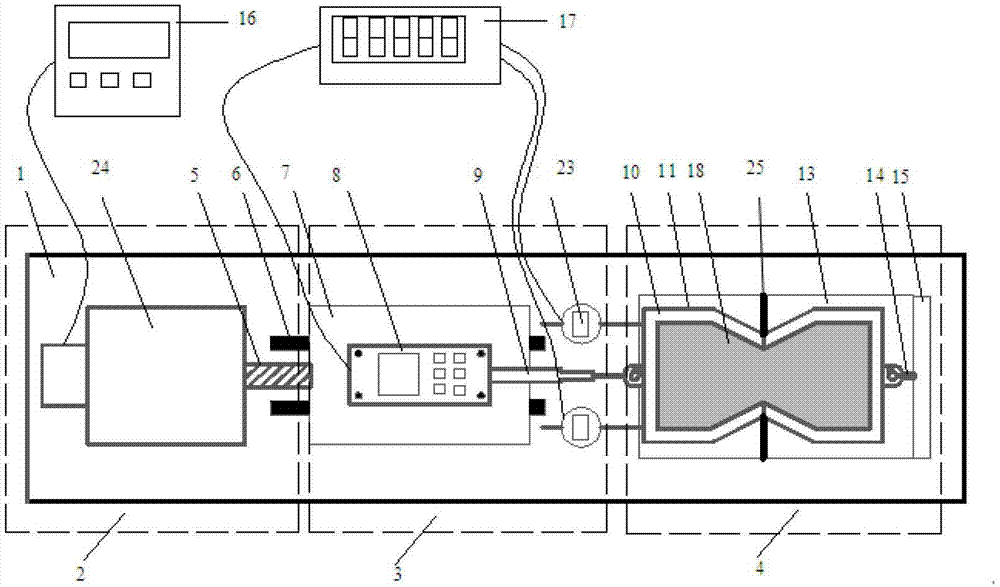
[0030] Example: as figure 1 As shown, the present invention includes a main body platform 1, a loading system 2, a measuring system 3 and a sample positioning and stretching system 4, and the loading system 2, the measuring system 3 and the sample positioning and stretching system 4 are all installed on the main body platform 1 .

[0031] like figure 1 figure 2 As shown, the loading system 2 includes a motor 24, a rigid transmission shaft 5 and a control box 16, and the measuring system 3 includes a guide rail 6, a slide rail guide block 7, a tension sensor 8, a displacement sensor 23, a data collector 17 and a rigid Connecting rod 9, the sample positioning and stretching system 4 includes an "8"-like retractor 10, a rolling platform 11, a ball 12, a fixed platform 13, a rigid fixed rod 14 and a rear fixed baffle 15, the motor 24 The control box 16 is connected with the control box 16 through wires. The function of the control box 16 is to control the power supply a...


PUM


Abstract

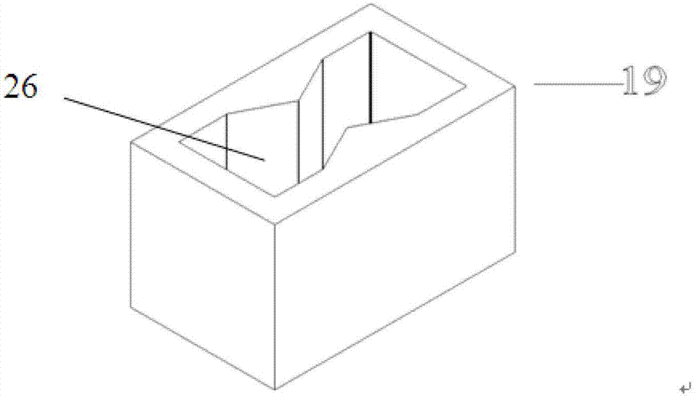
The invention discloses an 8-analogue-shaped soil uniaxial tensile tester comprising a main platform, a loading system, a measuring system, and a sample positioned drawing system. The tester is characterized in that the loading system, the measuring system, and the sample positioned drawing system are all arranged on the main platform; an 8-analogue-shaped sample is prepared through an 8-analogue-shaped sample-pressing mold and an 8-analogue-shaped sample-pressing piston; and during testing, the 8-analogue-shaped sample is drawn in an 8-analogue-shaped retractor. The tester provided by the invention adopts strain-controlled loading. Compared with a traditional uniaxial tensile tester, a complete soil tensile stress-strain curve can be obtained, and the influence of loading rates on soil tensile properties can be analyzed. According to the invention, the 8-analogue-shaped retractor is used for drawing the 8-analogue-shaped sample, and no auxiliary fixture is needed. Sample breakpoint position and fracture surface area are fixed, and test repeatability is good. According to the invention, the sample is prepared by full-area pressing by using the 8-analogue-shaped mold and piston, such that stresses on various parts of the sample are uniform, no artificial weak surface exists on a drawing direction, and testing precision is improved. The tester has the advantages of simple structure, simple operation, low cost, and reliable data.

Description

technical field [0001] The invention relates to an "8"-shaped soil body uniaxial tensile tester. Background technique [0002] Compared with the compressive and shear strength of the soil, the tensile strength is generally very small, especially for some soft soils or soils with high saturation, the tensile strength is usually only a few kPa or even close to 0. In the test It is difficult to make accurate measurements in engineering, and it is often ignored in engineering. In addition, most geological and geotechnical problems are related to compression deformation and shear failure of soil. Therefore, the tensile properties of soil were rarely considered in the theory of soil mechanics and engineering practice in the past. [0003] However, under some specific working conditions, it is not uncommon for the soil to bear tensile stress and fail. For example, the shrinkage cracks (cracks) developed in the soil in a dry environment are actually the result of tensile stress, ...

Claims


Application Information

Patent Timeline
Patent Type & Authority Applications(China)
IPC IPC(8): G01N3/08
Inventor 唐朝生施斌
Owner SUZHOU NANZEE SENSING TECH
Learn More