
Motion parameter measuring system calibration method and motion parameter measuring system based on position sensitive sensor

A technology of sensitive sensor and measurement system, applied in the field of measurement, can solve the problem of calculating the relationship between the output signal of the device and the coordinates of the actual spatial position, and achieve the effect of a high degree of automation and a simple method of use

Inactive Publication Date: 2013-01-30
BEIJING INSTITUTE OF TECHNOLOGYGY
View PDF3 Cites 0 Cited by
  • Summary
  • Abstract
  • Description
  • Claims
  • Application Information

AI Technical Summary

Problems solved by technology

At the same time, as a two-dimensional optical position sensor, PSD can sense the position of a larger two-dimensional space after adding an optical projection system, but in an actual system where the position of the main surface of the optical system is unknown, it is impossible to use a single detection Axial distance, calculate the relationship between the device output signal and the actual space position coordinates

Method used


Image

  • Motion parameter measuring system calibration method and motion parameter measuring system based on position sensitive sensor
  • Motion parameter measuring system calibration method and motion parameter measuring system based on position sensitive sensor
  • Motion parameter measuring system calibration method and motion parameter measuring system based on position sensitive sensor

Examples


example

[0056] Taking the rotationally symmetrical rigid body nutation measurement system of linear motion as an example, the calibration method of the measurement system based on PSD is described.

[0057] The nutation of a rigid body refers to the angle between the main trajectory of the rigid body and the axis of the instantaneous rigid body during the linear motion of the rigid body, such as Figure 5 shown.

[0058] The structure of the rigid body nutation measurement system is as follows: Figure 6 As shown, 17 represents the rigid body to be measured in this system, and the arrow points to the motion direction of the rigid body. Install two infrared LED indicator light sources at both ends of the rigid body, such as indicator light source 15 and indicator light source 16 in the figure. The advantage of choosing infrared LED as indicator light source is that it can avoid visible light interference to a certain extent. PSD6 and PSD7 are used to receive the light signal correspo...


PUM


Abstract

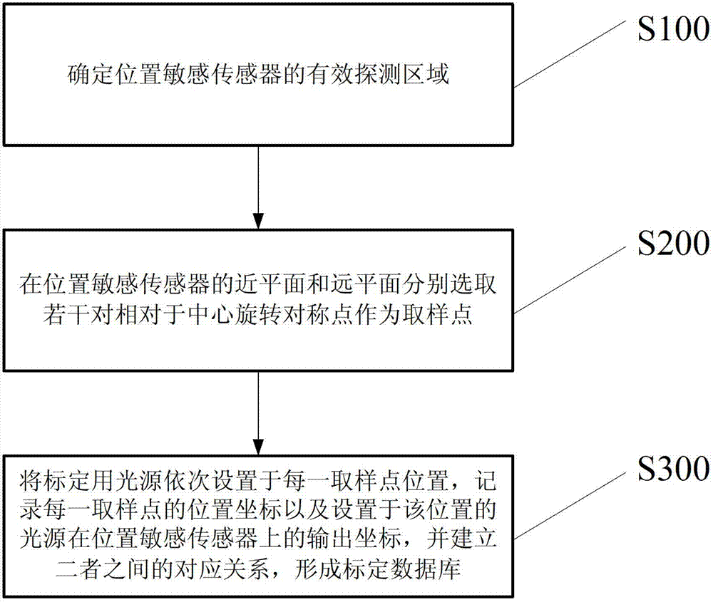
Disclosed is a motion parameter measuring system calibration method based on a position sensitive sensor. The method includes the following steps that (1) an effective detection area of the position sensitive sensor is determined; (2) a plurality of pairs of symmetry points which rotate relative to the center are selected on a near plane and a distant plane of the position sensitive sensor respectively to serve as sampling points, wherein the near plane and the distant plane refer to farthest end plane and nearest end plane of the effective detection area of the position sensitive sensor respectively along the axial direction; and (3) each light source for calibration is sequentially disposed at a position of one sampling point, the position coordinate of each sampling point is recorded, the output coordinate of each light source disposed at the position on the position sensitive sensor is recorded as well, and the corresponding relationship between the position coordinates and the output coordinates is established to form a calibration database. The calibration method has the advantages that the degree of automation is high, and a system can be used for performing an accurate three-dimensional measurement for positions of different depths after the calibration. Simultaneously the invention further provides a motion parameter measuring system based on the position sensitive sensor.

Description

technical field [0001] The invention belongs to the technical field of measurement, in particular to a calibration method of a motion parameter measurement system based on a position sensitive detector (Position Sensitive Detector, PSD). The invention also relates to a motion parameter measurement system based on a position sensitive sensor. Background technique [0002] Position Sensitive Detector (PSD) is a detector based on the transverse photoelectric effect, which is mostly used for position measurement of optical signals. For the two-dimensional PSD used in the motion parameter measurement system, a pair of output electrodes are respectively installed at both ends of the x and y directions. When the light from the measured object is incident on the photosensitive surface of the PSD, the four electrodes will output photocurrent, and the coordinates of the light spot can be calculated according to the four current values. After being processed by the PSD processing cir...

Claims


Application Information

Patent Timeline
IPC IPC(8): G01P21/00
Inventor 张雪静曹峰梅肖亮
Owner BEIJING INSTITUTE OF TECHNOLOGYGY
Learn More