Passive tag for electronic tag field

A technology of passive tags and dipole antennas, applied in the field of passive tags used in the field of electronic tags, can solve the problem of inability to complete the normal work of readers and tags, inability to sense external conditions and changes in real time, and inability to use RFID wireless Source tags and other issues, to achieve the effect of easy promotion and use, convenient processing, and easy realization

Inactive Publication Date: 2013-01-30
盛世铸成科技(北京)有限公司
View PDF4 Cites 0 Cited by
  • Summary
  • Abstract
  • Description
  • Claims
  • Application Information

AI Technical Summary

Problems solved by technology

When the energy provided by the reader is insufficient (that is, the transmission power is not large enough), or the energy received by the tag antenna is insufficient, the IC chip cannot work
This determines that the tag cannot be too far away from the reader, that is, the communication distance between the two cannot be too far, which further limits the use under many environmental conditions.
[0006] 2), the system undergoes information processing such as encoding, modulation, demodulation, decoding, etc., and it is prone to bit errors. Even if errors are corrected, the efficiency of information transmission will not be high
When the received electrical signal is lower than the starting level, the IC chip cannot work normally, and the normal work between the reader and the tag cannot be completed.
[0010] 6) At present, IC chips have the functions of reading, writing and rewriting, so the stored information is easy to be rewritten or miswritten, which leads to the low security of the stored information
[0011] 7) At present, the information that the IC chip can return to the reader is stored in the reader or system server in advance, and it cannot sense the external situation and changes in real time
For example, RFID passive tags cannot be used on some cheap small commodities

Method used


Image

  • Passive tag for electronic tag field

Examples


Embodiment Construction

[0037] The following will clearly and completely describe the technical solutions in the embodiments of the present invention with reference to the drawings in the embodiments of the present invention. Apparently, the described embodiments are only some of the embodiments of the present invention, not all of them. Based on the embodiments of the present invention, all other embodiments obtained by persons of ordinary skill in the art without making creative efforts belong to the protection scope of the present invention.

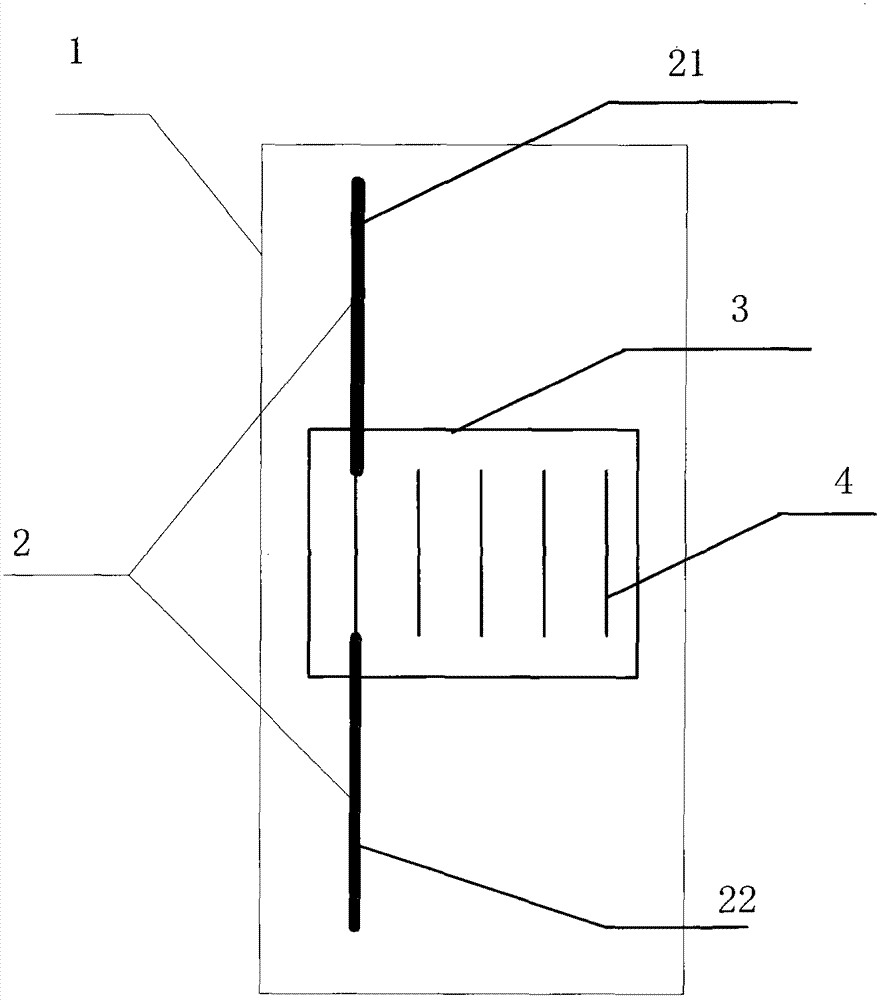
[0038] figure 1 It is a schematic structural diagram of a passive tag provided in the embodiment of this application.

[0039] like figure 1 As shown, the passive tag includes: a copper-clad substrate 1 , an antenna 2 and a dielectric board 3 , wherein: the antenna 2 and the dielectric board 3 are both located on the copper-clad substrate 1 .

[0040] In the embodiment of the present application, the material of the copper-clad substrate 1 can be polytetr...


PUM


Abstract

The application discloses a passive tag which comprises a copper-clad substrate, an antenna and a dielectric slab, wherein the antenna and the dielectric slab are all positioned on the copper-clad substrate; the antenna comprises an antenna upper arm and an antenna lower arm; the antenna upper arm and the antenna lower arm are positioned on the same straight line; a gap is formed between the antenna upper arm and the antenna lower arm; a plurality of metal wires which are parallel to each other and between two of which a gap is formed are arranged on the dielectric slab; the extending direction of the metal wire is parallel to the antenna upper arm and the antenna lower arm; and the separated end parts of the antenna upper arm and the antenna lower arm are respectively connected with two ends of a metal wire in the plurality of metal wires. The passive tag does not have a working threshold, is long in communication distance, safe, reliable, small in size, convenient to process, low in cost and convenient to popularize and use, wherein the cost of a reader-writer can be reduced obviously.

Description

technical field [0001] The present invention relates to the technical field of RFID, and more specifically relates to a passive tag. Background technique [0002] At present, the RFID passive tags in the industry are composed of an antenna and an IC chip in terms of electrical performance. The working principle and process are: [0003] The reader emits carrier signals with information (such as read and write commands, status commands, etc.) through its own antenna, and transforms them into electromagnetic waves in the surrounding space; the tag antenna receives electromagnetic waves from the surrounding field and converts them into Electrical signals (voltage, current, etc.). Part of this electrical signal is rectified and filtered by the IC chip, and used as the working power of the IC chip; part of it is demodulated and decoded by the IC chip, and used as an instruction to determine the subsequent working state of the IC chip, such as writing information into the IC chi...

Claims


Application Information

Patent Timeline
Patent Type & Authority Applications(China)
IPC IPC(8): G06K19/077
Inventor 程胜祥陈业军
Owner 盛世铸成科技(北京)有限公司
Why Eureka
Try Eureka