Illumination optical system and projector using same

A lighting optical system and technology of optical components, applied in the field of projectors, can solve problems such as increasing the amount of light, and achieve the effects of long operating life, high brightness, and low etendue

Inactive Publication Date: 2013-01-30
NEC DISPLAY SOLUTIONS LTD
View PDF7 Cites 9 Cited by
  • Summary
  • Abstract
  • Description
  • Claims
  • Application Information

AI Technical Summary

Problems solved by technology

However, for light sources using LEDs, it is difficult to increase the amount of light without increasing the light emitting area

Method used


Image

  • Illumination optical system and projector using same
  • Illumination optical system and projector using same
  • Illumination optical system and projector using same

Examples


Embodiment Construction

[0027] Exemplary embodiments of the present invention will be described below with reference to the accompanying drawings. In the following explanation, components having the same function are assigned to the same reference numerals and explanation thereof may be omitted.

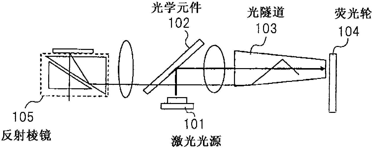
[0028] figure 1 is a block diagram showing the configuration of an illumination optical system according to an exemplary embodiment of the present invention.

[0029] Such as figure 1 As shown in , the illumination optical system of the exemplary embodiment includes a laser light source 101 , an optical element 102 , a light tunnel 103 , a fluorescent wheel 104 and a reflective prism 105 .

[0030] A laser light source 101 generates laser light serving as excitation light having a wavelength λ1. Laser light generated by laser light source 101 is reflected by optical element 102 , passes through light tunnel 103 , and enters fluorescent wheel 104 .

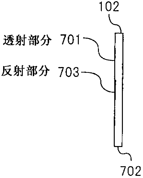
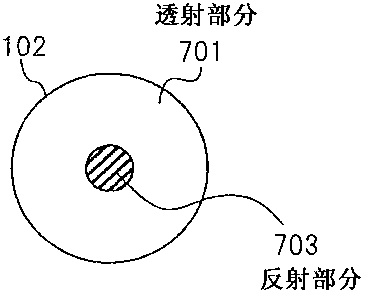
[0031] The optical element 102 is located in the beam ...


PUM


Abstract

The present disclosures achieve an illumination optical system that has small etendue, a longer service life, and higher brightness, and that is provided with: a laser light source that generates excitation light; a fluorescent body that generates fluorescent light by means of the aforementioned excitation light; a light tunnel that radiates the aforementioned excitation light that enters one end thereof towards the aforementioned fluorescent body from the other end, and that radiates the fluorescent light generated by the aforementioned fluorescent body from the aforementioned one end; and an optical element that is provided in the light path of the aforementioned laser light source and the aforementioned light tunnel, reflects the aforementioned excitation light, and transmits the aforementioned fluorescent light.

Description

technical field [0001] The present invention relates to an illumination optical system for generating illumination light of various colors to form image light of various colors, and a projector for projecting the image light provided by the illumination optical system. Background technique [0002] Attention has been paid to technologies utilizing LEDs (Light Emitting Diodes: Light Emitting Diodes) as light sources for projectors for projecting images on screens, such as liquid crystal projectors and DMD (Digital Micromirror Device: Digital Micromirror Device) projectors (See Patent Document 1). [0003] A projector having an LED as a light source offers the advantage of a longer operating life and higher reliability due to the longer operating life and higher reliability of the LED. [0004] However, since the light from the LED has low luminance as light for the projector, an image with sufficient luminance cannot be easily obtained in a projector having the LED as a ligh...

Claims


Application Information

Patent Timeline
Patent Type & Authority Applications(China)
IPC IPC(8): G03B21/14F21S2/00G02B5/26G03B21/00
CPCH04N9/3161G03B21/14G03B21/204H04N9/3114G02B2207/113H01S5/4012G02B5/26G02B26/008H01S5/005H01S3/005G03B33/08G03B21/2033H01S5/0087H01S5/0071H01S5/32341
Inventor 加藤厚志
Owner NEC DISPLAY SOLUTIONS LTD
Why Eureka
Try Eureka