Semi-automatic pipe feeding machine

A semi-automatic, pipe machine technology, applied in pipe cutting devices, metal processing machinery parts, clamping and other directions, can solve the problems of easy scratching of chips, low cutting efficiency, etc., and achieve low labor intensity, high production efficiency, and easy operation. Effect

Inactive Publication Date: 2013-02-06
宁波培源股份有限公司
View PDF5 Cites 6 Cited by
  • Summary
  • Abstract
  • Description
  • Claims
  • Application Information

AI Technical Summary

Problems solved by technology

[0004] The technical problem to be solved by the present invention is to provide a semi-automatic pipe lowering machine, which solves the problems of low cutting efficiency and easy scratching of the surface of the workpiece by cutting chips in the existing cutting method

Method used


Image

  • Semi-automatic pipe feeding machine
  • Semi-automatic pipe feeding machine

Examples


Embodiment Construction

[0021] The specific implementation manners of the present invention will be further described in detail below in conjunction with the accompanying drawings and embodiments. The following examples are used to illustrate the present invention, but are not intended to limit the scope of the present invention.

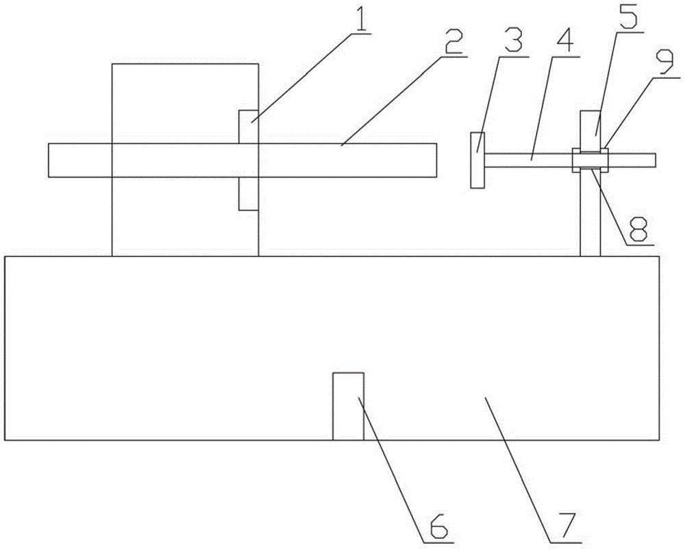
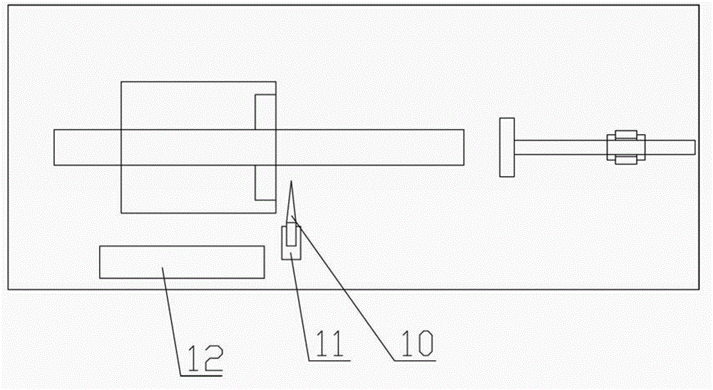
[0022] Such as figure 1 and figure 2 A kind of semi-automatic pipe lowering machine shown, comprises frame 7, length positioning device, clamping device; The length positioning device and clamping device are installed on frame 7, and clamping device clamps pipe material 2, and length positioning device limits tube The length of the material 2, a cutting device for cutting the tube material 2 is provided in front of the clamping device.

[0023] The length positioning device comprises a column 5 and a threaded rod 4, the column 5 is provided with a threaded hole 8, the threaded rod 4 is installed on the threaded hole 8, the threaded rod 4 is provided with bolts 9 positio...


PUM


Abstract

The invention discloses a semi-automatic pipe feeding machine which comprises a machine frame (7), a length positioning device and a clamping device, wherein the length positioning device and the clamping device are arranged on the machine frame (7), the clamping device is used for clamping pipes (2), the length positioning device is used for limiting the length of the pipes (2), and a cutting device used for cutting the pipes (2) is arranged in front of the clamping device. The semi-automatic pipe feeding machine is high in work efficiency, simple in device process and low in labor intensity.

Description

technical field [0001] The invention belongs to the field of pipe material processing equipment, and in particular relates to a semi-automatic pipe lowering machine. Background technique [0002] At present, in the production and processing of steel pipes, the cutting methods of steel pipes mainly include sawing machine sawing, grinding wheel cutting, roller extrusion, etc. These steel pipe cutting methods have low cutting efficiency, rough incision, large cutting noise, and severe cutting problems to varying degrees. Shortcomings such as poor length accuracy and excessive cutting. Contents of the invention [0003] (1) Technical problems to be solved [0004] The technical problem to be solved by the present invention is to provide a semi-automatic tube lowering machine, which solves the problems of low cutting efficiency and easy scratching of the workpiece surface by cutting chips in the existing cutting method. [0005] (2) Technical solution [0006] In order to so...

Claims


Application Information

Patent Timeline
Patent Type & Authority Applications(China)
IPC IPC(8): B23D21/00B23Q3/00
Inventor 陈德行张增魁
Owner 宁波培源股份有限公司
Why Eureka
Try Eureka