Electric packing machine

An electric and battery technology, which is applied to the parts of the strapping machine and strapping materials, etc., can solve the problems of damage to the bundled objects, increase the restriction, and work blockage, etc., and achieve strong packing fastness, compact structure, and compact structure strong effect

Active Publication Date: 2013-02-06
浙江维派包装设备有限公司
View PDF7 Cites 6 Cited by
  • Summary
  • Abstract
  • Description
  • Claims
  • Application Information

AI Technical Summary

Problems solved by technology

[0002] Electric balers are widely used in food, medicine, hardware, chemical, clothing, postal and other industries, suitable for carton packaging, paper packaging, parcel letter packaging, medicine box packaging, light industry packaging, hardware tools packaging, ceramic products packaging, auto parts packaging Automatic packaging and binding of various sizes of goods such as daily chemical products packaging, stationery packaging, equipment packaging, etc.; its general working principle: After wrapping the packaged objects from top to bottom, put the joint of the packaging belt into the machine to work In the groove, the tightening wheel is driven by the motor to tighten the strap, and the strap is bonded by friction as a buckle, and finally the strap is automatically cut. Such an electric strapping machine has: high flexibility, fast, safe and easy , environmental protection and other advantages, but the structure of its electric baler is copied, because after it is welded, the baler is directly pulled out, but it is difficult to pull out the baler after tensioning, which is easy to cause damage to the package, and the existing electric baler In the baler technology, its power supply is a battery, so that if the battery power is insufficient, it is difficult to continue working and cause work blockage, which increases its limitation.

Method used


Image

  • Electric packing machine
  • Electric packing machine
  • Electric packing machine

Examples


Embodiment Construction

[0026] In order to have a further understanding and understanding of the structural features of the present invention and the achieved effects, the preferred embodiments and accompanying drawings are used for a detailed description, as follows:

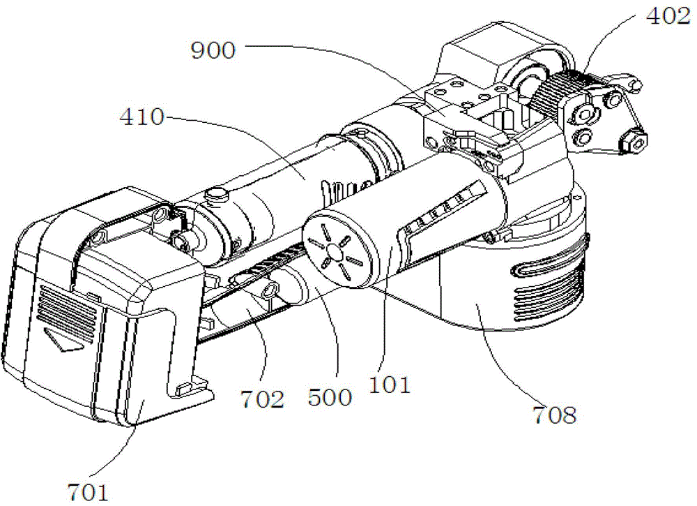
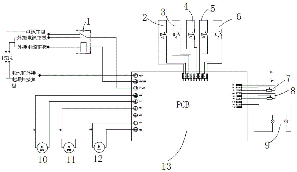
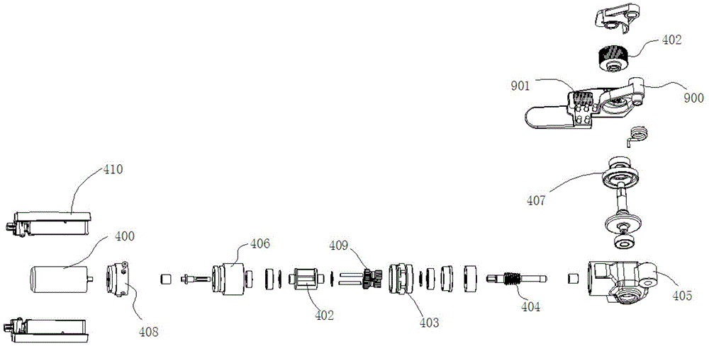
[0027] refer to figure 1 An electric baler, comprising a battery 700, a body, a handle 702, a tensioning device, a tape cutting device, a welding device and a control board, the control board 13 is provided with a relay, and a bottom plate 900 is fixed at the lower part of the body, the bottom board The 900 is equipped with a welding tooth plate and a 901 tensioning tooth plate, refer to image 3 , 4 and 5,: the tensioning device includes a tensioning motor 400, a reduction box 405 and a tensioning wheel 402, the tensioning motor 400 is placed in the handle 702 and is connected with the reduction box 405 through a connecting sleeve 406, and the pulling The tight wheel 402 is connected to the reduction box 405, and the reduction box ...


PUM


Abstract

The invention relates to an electric packing machine comprising a battery, a body, a handle, a tensioning device, a band cutting device, a fusion welding device and an electric control board, wherein a relay is arranged on the electric control board, a corresponding tensioning motor, a band cutting motor and a fusion welding motor coordinate with the electric control board to control the operation, a jack module is connected between the battery and the electric control board in parallel, and a rewinding switch module and a potentiometer knob module are arranged on the electric control board to control the fusion welding and the tensioning band; according to the invention, the brand new tensioning device, the band cutting device and the fusion welding device are used for realizing the packing procedures of band-shaped wires such as PET (polyethylene terephthalate) bands and PP (Propene Polymer) bands, so that the electric packing machine has the advantages of compact structure, strong structure compactness and strong packing firmness, and the like, and meanwhile, a power supply is designed to double power supplies of battery and jack so as to selectively utilize the power supply of the packing machine under different environments.

Description

technical field [0001] The invention relates to a packing machine, which belongs to the field of packing equipment, and in particular relates to an electric packing machine with a socket, a battery and a rewinding function. Background technique [0002] Electric balers are widely used in food, medicine, hardware, chemical, clothing, postal and other industries, suitable for carton packaging, paper packaging, parcel letter packaging, medicine box packaging, light industry packaging, hardware tools packaging, ceramic products packaging, auto parts packaging Automatic packaging and binding of various sizes of goods such as daily chemical products packaging, stationery packaging, equipment packaging, etc.; its general working principle: After wrapping the packaged objects from top to bottom, put the joint of the packaging belt into the machine to work In the groove, the tightening wheel is driven by the motor to tighten the strap, and the strap is bonded by friction as a buckle,...

Claims


Application Information

Patent Timeline
Patent Type & Authority Applications(China)
IPC IPC(8): B65B13/02B65B13/22B65B13/32
Inventor 何瑜华
Owner 浙江维派包装设备有限公司
Why Eureka
Try Eureka