Induced crack structure of frame bridge

A technology for inducing joints and frame bridges, applied in bridges, bridge parts, bridge construction, etc., can solve the problems of poor water-stopping effect of frame joints, increased cumulative deviation of jacking, and more cracks, so as to reduce construction costs. , the structure is simple, the effect of shortening the construction period

Active Publication Date: 2013-02-06
RAILWAY NO 10 ENG GRP CO LTD
View PDF5 Cites 5 Cited by
  • Summary
  • Abstract
  • Description
  • Claims
  • Application Information

AI Technical Summary

Problems solved by technology

[0003] Aiming at the above-mentioned defects existing in the prior art, the present invention provides an induced joint structure of a frame bridge, which can effectively solve the problem of long construction period for multi-stage prefabrication of the frame, increased accumulative deviation of jacking caused by multiple jackings, and problems caused by concrete stress. Many cracks and poor sealing effect of frame joints

Method used


Image

  • Induced crack structure of frame bridge
  • Induced crack structure of frame bridge
  • Induced crack structure of frame bridge

Examples


Embodiment 1

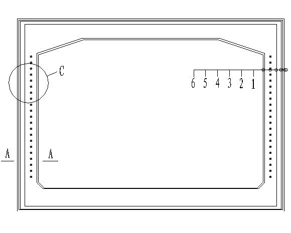
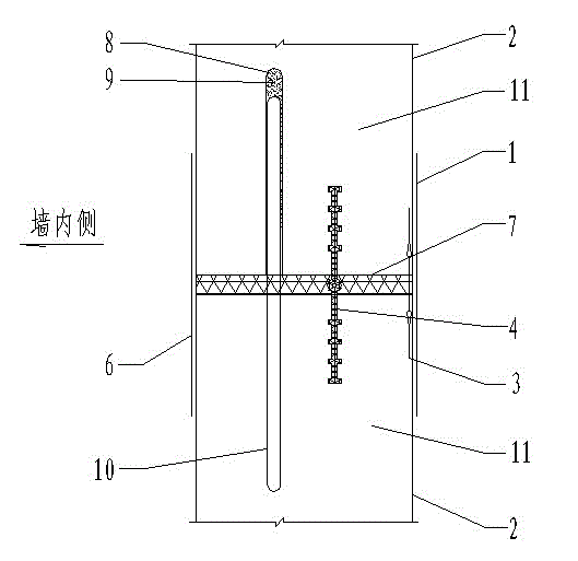
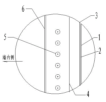
[0022] as attached Figure 1-3 As shown, a frame bridge induced joint structure, the induced joint is arranged in the frame, the caulking plate 7 is arranged in the described induced joint, and the frame height direction is spaced along the frame height direction in the side walls on both sides of the frame at the induced joint. A number of steel shear pins 5 are arranged along the length of the frame. The steel shear pins 5 are composed of an iron sleeve 8 with an inner diameter of 30 mm and a round steel 10 with a diameter of φ28 mm. The round steel 10 passes through the caulking plate 7 and is inserted into the iron sleeve 8, the other end of the iron sleeve 8 is a closed end, which is filled with asphalt ointment 9, and the non-closed end of the iron sleeve 8 is flush with the surface of the caulking plate 7. The induced seam is also embedded with a steel edge waterstop 3 forming a closed loop along the induced joint on the outside of the frame reinforcement, and a rubber ...

Embodiment 2

[0030] as attached Figure 4-6 As shown, this embodiment is basically the same as Embodiment 1, the difference is that no steel edge waterstop and rubber waterstop are provided in this embodiment. It includes induction joints arranged in the frame bridge, and caulking plates 7 are arranged in the induction joints. In the side walls on both sides of the frame at the induction joint, several steel shear pins 5 arranged along the length direction of the frame are arranged at intervals along the height direction of the frame. The round steel 10 is composed of round steel 10, which passes through the caulking plate 7 and is inserted into the iron sleeve 8. The other end of the iron sleeve 8 is a closed end, which is filled with asphalt ointment 9, and the non-closed end of the iron sleeve 8 The end is flush with the surface of caulking plate 7. A polyurethane waterproof coating layer 2 and a chlorinated polyethylene waterproof coiled material layer 1 are sequentially arranged on ...


PUM

PropertyMeasurementUnit
diameteraaaaaaaaaa

Abstract

The invention discloses an induced crack structure of a frame bridge, which is an induced crack structure arranged in a frame bridge and used for improving stress cracks in concrete of a long box jacking frame and a water seepage phenomenon at joints of frame sections, and belongs to the technical field of jacking construction. The induced crack structure comprises an induced crack arranged in the frame bridge, a crack filling plate (7) is arranged in the induced crack, a plurality of steel shear pins (5) arranged along the length direction of a frame are arranged in side walls on both sides of the frame at the induced crack along the height direction of the frame at a certain interval, the steel shear pins (5) pass through the crack filling plate (7), and the outer side of a top plate of the induced joint, the outer sides of the side walls on both sides of the frame and the inner side of the frame are respectively provided with a waterproof layer. The induced crack structure disclosed by the invention is simple in structure, and can effectively improve a phenomenon that a concrete frame structure has more cracks under the influence of concrete stress, therefore, the accumulative jacking deviation generated by the multiple jacking of a multi-section frame is greatly reduced, and the project quality is improved, meanwhile, the construction period can be greatly shortened, and the construction cost can be reduced.

Description

technical field [0001] The invention relates to an induced joint structure of a frame bridge, in particular to an induced joint structure arranged in a frame bridge to improve the concrete stress cracks in the jacking frame of a long box body and water seepage at the joint joints of the frame, and belongs to the technical field of jacking construction. Background technique [0002] During frame jacking construction, if the length of the jacking frame is relatively long, it is usually prefabricated in multiple sections and then jacked by the intermediate method, which requires a longer construction period, and the cumulative deviation of jacking will increase after the number of jackings increases; Or use the prefabrication of the entire length of the frame, although the construction period can be shortened in this way, but there will be more cracks in the frame structure due to the influence of concrete stress, and the quality cannot be guaranteed. In the past, settlement jo...

Claims


Application Information

Patent Timeline
Patent Type & Authority Applications(China)
IPC IPC(8): E01D19/00E01D19/08
Inventor 杨基好踪高峰吴强马小伟
Owner RAILWAY NO 10 ENG GRP CO LTD
Why Eureka
Try Eureka