
Eureka
For R&D, Eureka makes reading and utilizing patents & technical documents easy.
Eureka AIR
Designed for self-driven R&D workflows. Generate viable solutions, solve complex R&D challenges, empower your innovation with AI.

Eureka Materials
Designed for material experts only. Revolutionize your material R&D, from search, analyze, to developing new materials.

TechResearch
Generate reliable direction feasibility study reports for your R&D in just a few steps.

TechSeek
Discover and master advanced knowledge NOW. Basics, ideas, possibilities, all at once.

TechMind
As an expert in R&D Theories, TechMind can generates customized viable solutions instantly.

TechRisk
Analyze your overall solution with one click, know your potential R&D risks in advance.

TechMonitor
Get weekly tech updates, stay abreast of the latest tech innovations and key insights.
Wafer drying equipment and forming method thereof
A wafer drying and equipment technology, applied in drying solid materials, lighting and heating equipment, drying, etc., can solve the problems of high cost and poor quality, and achieve the effect of low cost, good quality and uniform thickness
- Summary
- Abstract
- Description
- Claims
- Application Information
AI Technical Summary
Problems solved by technology
Method used
Image

Examples
Embodiment Construction
[0035] As mentioned in the background, the wafer drying equipment in the prior art has high cost and poor quality.
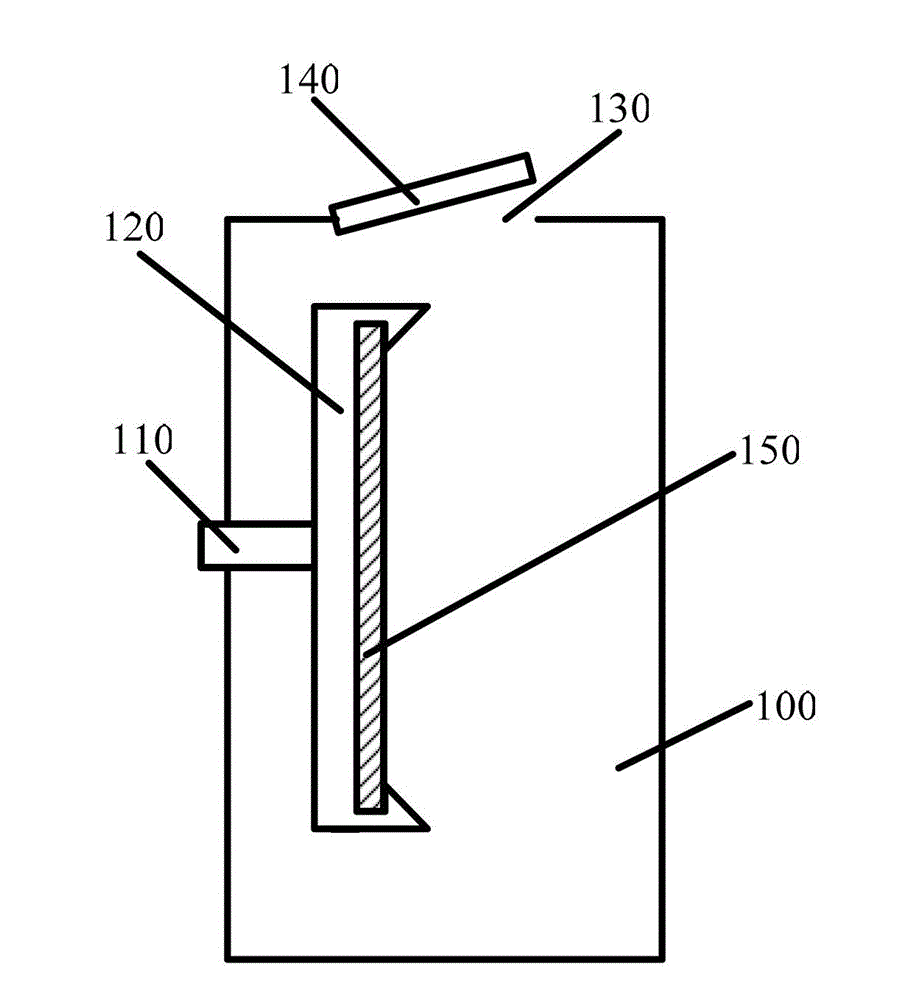
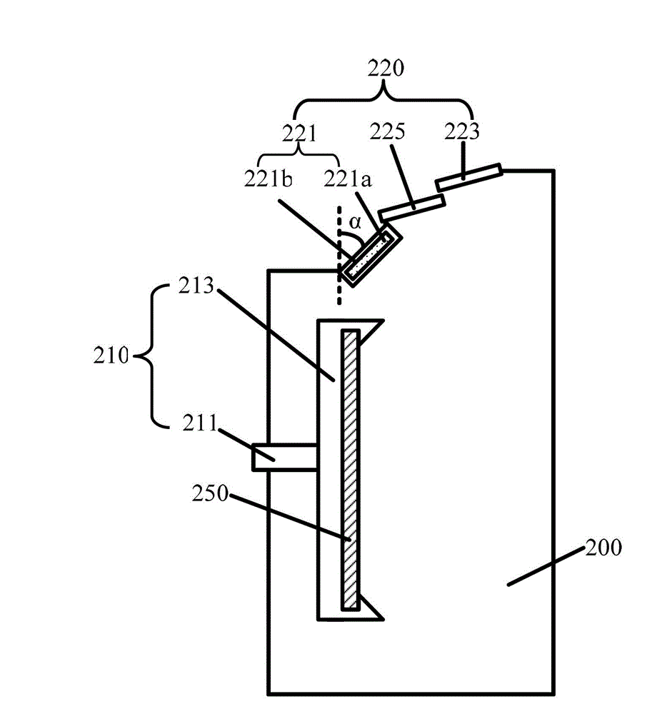
[0036] After research, the inventors found that the baffles of the wafer drying device in the prior art are made of high-cost and easily broken quartz glass, and workers can easily damage the baffles during transportation, installation or disassembly. Normal operation of the wafer drying unit.
[0037] If the baffle plate of the wafer drying device is replaced with an unbreakable material, the cost can be greatly reduced and the normal operation of the wafer drying device can be guaranteed. After further research, the inventors found that the wafers put into the wafer drying device are usually just taken out of the cleaning device, and the surface of the wafer taken out of the cleaning device still has cleaning liquid. In the cleaning liquid, in addition to In addition to large amounts of moisture, hydrofluoric acid (HF) is usually included. Put the wafer with...
PUM
 Abstract
Description
Claims
Application Information
 - R&D Engineer
- R&D Manager
- IP Professional
- Industry Leading Data Capabilities
- Powerful AI technology
- Patent DNA Extraction
Browse by: Latest US Patents, China's latest patents, Technical Efficacy Thesaurus, Application Domain, Technology Topic, Popular Technical Reports.
© 2024 PatSnap. All rights reserved.Legal|Privacy policy|Modern Slavery Act Transparency Statement|Sitemap|About US| Contact US: help@patsnap.com