Light-splitting synchronous phase shifting interference microscopy device and detection method

A synchronous phase-shifting and interference microscopy technology, applied in the direction of measuring devices, optical devices, instruments, etc., can solve the problems of low measurement accuracy, complicated and difficult operation, etc., and achieve the effect of simple mapping relationship, convenient and flexible operation, and improved efficiency

Inactive Publication Date: 2013-02-06
HARBIN ENG UNIV
View PDF5 Cites 16 Cited by
  • Summary
  • Abstract
  • Description
  • Claims
  • Application Information

AI Technical Summary

Problems solved by technology

[0006] The purpose of the present invention is to provide a light-splitting synchronous phase-shifting interference microscopic detection device and detectio

Method used


Image

  • Light-splitting synchronous phase shifting interference microscopy device and detection method
  • Light-splitting synchronous phase shifting interference microscopy device and detection method
  • Light-splitting synchronous phase shifting interference microscopy device and detection method

Examples


specific Embodiment approach 1

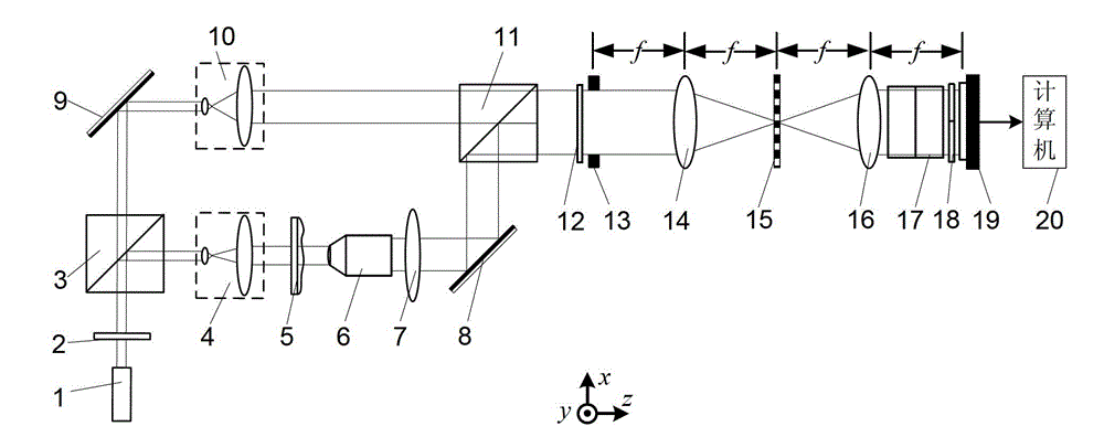
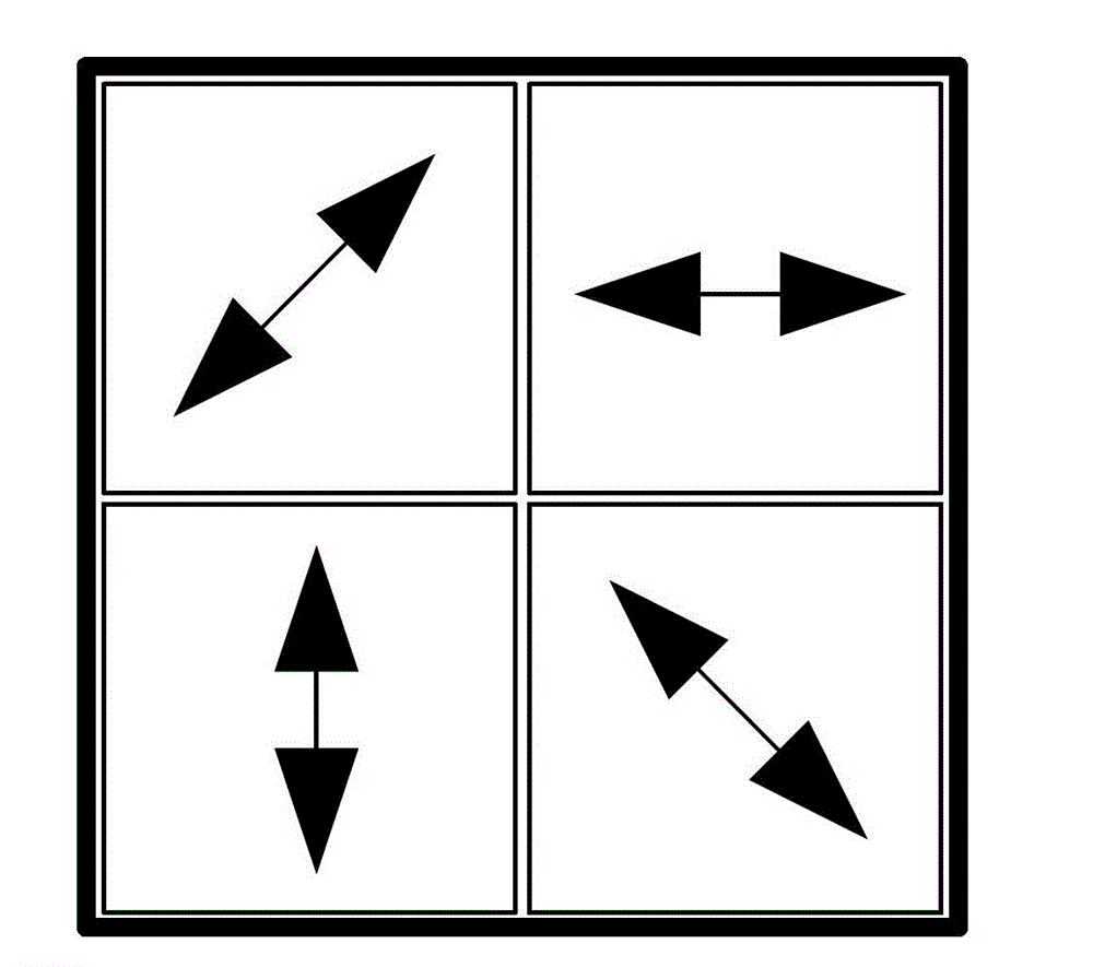
[0034] Specific implementation mode one: the following combination Figure 1 to Figure 4 Describe the present embodiment, the spectroscopic synchronous phase-shifting interference microscopic detection device described in the present embodiment, it comprises light source 1, and it also comprises polarizer 2, the first polarizing beam splitting prism 3, the first collimating beam expander system 4, to-be-measured Object 5, microscope objective lens 6, correction objective lens 7, first mirror 8, second mirror 9, second collimator beam expander system 10, second polarization beam splitter prism 11, λ / 4 wave plate 12, rectangular window 13 , a first Fourier lens 14, a one-dimensional periodic grating 15, a second Fourier lens 16, a depolarizing beamsplitter prism 17, a four-quadrant polarizer group 18, an image sensor 19 and a computer 20, where λ is the light beam emitted by the light source 1 wavelength of light,

[0035] The light beam emitted by the light source 1 enters the...

specific Embodiment approach 2

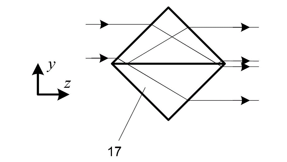
[0045] Specific implementation mode two: the following combination figure 2 Describe this embodiment mode, this embodiment mode will be further described to Embodiment 1, the depolarization dichroic prism 17 is placed according to the mode that its dichroic surface is parallel to the plane formed by x-axis and z-axis, and the incident light is from 45° or -45° to its dichroic plane. ° Angle of incidence.

specific Embodiment approach 3

[0046] Embodiment 3: In this embodiment, Embodiment 1 or Embodiment 2 is further described. The one-dimensional periodic grating 15 is a binary one-dimensional periodic grating or a sine one-dimensional periodic grating or a cosine one-dimensional periodic grating.

[0047] In this embodiment, the one-dimensional periodic grating 15 adopts a Ronchi grating with period d=50 μm.


PUM


Abstract

The invention discloses a light-splitting synchronous phase shifting interference microscopy device and a detection method, belonging to the field of the optical interference detection. The invention aims to solve the problems of difficulty and complexity in operation and low measurement precision of the traditional optical phase shifting interference detection method. The scheme is that a light beam emitted from a light source is divided into an object light beam and a reference light beam, of which the polarization directions are mutually vertical, after passing through a polarizing film and a first polarization light splitting prism; after gathered by a second polarization light splitting prism, the object light beam and the reference light beam successively pass through a lambda/4 wave plate, a rectangular window, a first Fourier lens, a one-dimensional period grating, a second Fourier lens, a depolarization light splitting prism and a four-quadrant polarizing film group; a polarization light beam emitted from the four-quadrant polarizing film group generates an interference pattern on the plane of an image sensor; the collected interference pattern is processed by a computer; and the phase distribution of an object to be detected is obtained.

Description

technical field [0001] The invention relates to a light-splitting synchronous phase-shifting interference microscopic detection device and a detection method, belonging to the field of optical interference detection. Background technique [0002] Interference microscopy combines interference technology and microscopic magnification technology, which can accurately analyze the three-dimensional shape of objects and the phase information of phase-type objects. It is an ideal method for measuring the three-dimensional shape and phase distribution of tiny objects. [0003] In 2006, the Swiss company Lyncee Tec launched the DHM-1000 digital holographic microscope for the first time, which can be used to measure the three-dimensional shape and phase distribution of tiny objects. However, due to the off-axis holographic optical path, the CCD resolution and spatial bandwidth product cannot be fully utilized; at the same time, the phase distortion caused by the objective lens cannot...

Claims


Application Information

Patent Timeline
IPC IPC(8): G01B9/02G01B11/06
Inventor 单明广钟志郝本功张雅彬窦峥刁鸣
Owner HARBIN ENG UNIV
Why Eureka
Try Eureka