A method of robot head-eye coordinated motion control based on bionic mechanism

A technology of coordinated control and robotics, applied in the field of robotic bionics, can solve problems such as complex calculation algorithms of luminous flux energy functions, difficulty in application, interference, etc., and achieve the effect of enhancing naturalness, reducing difficulty, and stabilizing image information

Active Publication Date: 2016-03-30
精海智能装备有限公司
View PDF3 Cites 0 Cited by
  • Summary
  • Abstract
  • Description
  • Claims
  • Application Information

AI Technical Summary

Problems solved by technology

However, this method is extremely susceptible to interference from the environment, and the calculation algorithm of the luminous flux energy function is very complicated, so it is difficult to apply it in real time in a dynamic environment

Method used


Image

  • A method of robot head-eye coordinated motion control based on bionic mechanism
  • A method of robot head-eye coordinated motion control based on bionic mechanism
  • A method of robot head-eye coordinated motion control based on bionic mechanism

Examples


Embodiment 1

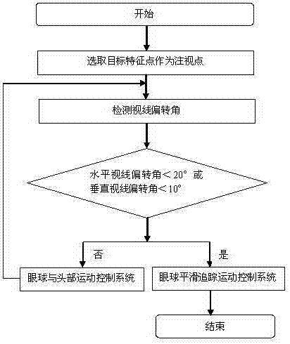
[0028] see figure 1 and figure 2 , the robot head-eye coordination control method based on the bionic mechanism, is characterized in that the rotation angles of the robot's head and eyes are controlled by their respective mathematical models, the size of the eye rotation angle is controlled by the binocular eye movement control system model, and the head and neck rotation angle is controlled by the head The model control of the internal motion control system dynamically adjusts the head-eye rotation angle according to the deflection angle; the specific steps are as follows:

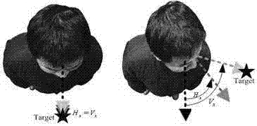
[0029] 1) Select the target feature point as the fixation point: the head-eye coordination bionic vision system selects the target feature point as the fixation point, and the eyes focus on the fixation point;

[0030] 2) Detection of sight deflection angle: When the target point is out of the center of the image plane, the head-eye coordination system detects the size of the sight deflection angle in r...

Embodiment 2

[0034] This embodiment is basically the same as Embodiment 1, and the special features are as follows:

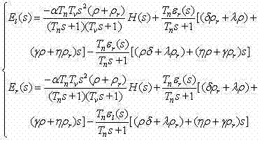
[0035] The eyeball smooth tracking movement and vestibulo-ocular movement reflex movement model described in step 3) and step 4) are:

[0036]

[0037] in, is the rotation angle of the target around the neck, is the head rotation angle, is the rotation angle of the eyeball, is the time constant of the vestibular nerve, according to physiological experiments = 16 seconds, is the time constant of the integrator, according to the physiological experiment = 25 seconds, , is the retinal sliding displacement, subscript and represent left and right respectively, according to physiological experiments , , , , , , . The head motion control model described in step 4) is:

[0038]

[0039]

[0040] in , Represents the head rotation angle and line-of-sight deflection angle when the head rotates horizontally, , Represents the head rota...

Embodiment 3

[0042] Here we take a tennis ball as an example to illustrate; the specific steps are as follows:

[0043] 1. First, the head-eye coordination bionic vision system selects the center of mass of the tennis ball as the spatial fixation point, and the eyes focus on the fixation point;


PUM


Abstract

The invention belongs to the technical field of bionics of robots, and relates to a robot head-eye coordination motion control method based on a bionic principle. According to the method, angles of rotation of a head and eyes are respectively controlled by each of mathematic models, angles of rotation of eyeballs are controlled by a binocular eyeball motion control system model, angles of rotation of head and neck are controlled by a head motion control system model, and the angles of rotation of the head and the eyes are dynamically adjusted according to an angle of deflection. With the adoption of the control method provided by the invention, the visual range of the robot can be enlarged so that the robot can watch or track an object in a large range; and the naturalness of human-computer interaction, such as the eye contact and the emotional exchange during the conversation with the robot, can be enhanced, and a reference can be provided for the head-eye coordination motion of the humanoid robot.

Description

technical field [0001] The invention relates to the field of robot bionics, in particular to a robot head-eye coordinated motion control method based on the principles of human eye physiology and anatomy and combined with the characteristics of human head motion behavior. Background technique [0002] So far, although various intelligent head-eye coordination robots have come out one after another, their head-eye coordination movement control functions are still relatively weak. Most of them start from the perspective of stereo vision, and their control strategy is to obtain the desired movement angle of the head and eyes by capturing the three-dimensional pose of the space object, so as to realize the coordinated movement of the head and eyes. For example, there is an article report, its title is: Robothead motion control with anemphasis realism of neck - eye coordination during object tracking (the author of the article is: Rajruangrabin Jan and PopaDO. Published in the jo...

Claims


Application Information

Patent Timeline
Patent Type & Authority Patents(China)
IPC IPC(8): G05D3/12
Inventor 谢少荣李树平程军李恒宇罗均
Owner 精海智能装备有限公司
Why Eureka
Try Eureka