Eureka AIR delivers breakthrough ideas for toughest innovation challenges, trusted by R&D personnel around the world.

Motor with brake and overload protection

An overload protection and overload protector technology, applied in emergency protection circuit devices, electromechanical devices, electrical components, etc., can solve the problems of accelerated aging of wires and electronic components, heavy motor rotor weight, poor structural compactness, etc., and achieve light weight. , reduce inertia, good reliability

Active Publication Date: 2013-02-06
ZHEJIANG XINLI ELECTRIC APPLIANCE TECH CO LTD
View PDF6 Cites 7 Cited by
  • Summary
  • Abstract
  • Description
  • Claims
  • Application Information

AI Technical Summary

Problems solved by technology

[0008] The first purpose of the present invention is to provide a motor with brake and overload protection that has overload protection function and does not cause the shaft to be broken due to impact. , the problem that the rotating shaft will be broken due to an instant impact, and the overload protection through electrical components will lead to accelerated aging of wires and electronic components, poor timeliness, and poor reliability.
[0009] The second purpose of the present invention is to provide a motor with brake and overload protection that can complete heat dissipation work without installing a fan, which not only solves the problem of low control precision caused by heavy weight and large inertia of the motor rotor, but also solves the problem of low control accuracy through The problem of poor structural compactness caused by external fans for heat dissipation

Method used


Image

  • Motor with brake and overload protection
  • Motor with brake and overload protection
  • Motor with brake and overload protection

Examples


Embodiment Construction

[0027] The present invention will be further described below in conjunction with the accompanying drawings and embodiments.

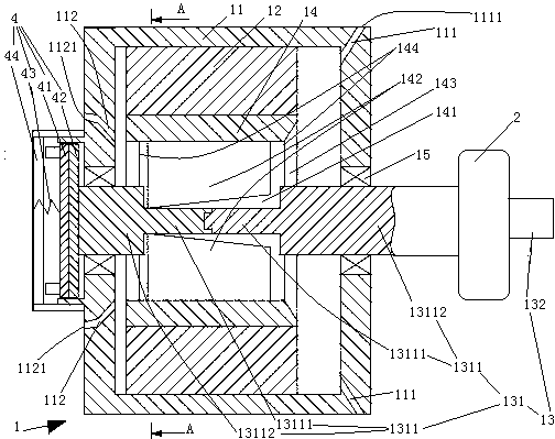
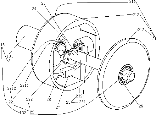
[0028] see figure 1 , a motor with brake and overload protection, including a motor body 1, a brake mechanism 4 and a hydraulic overload protector 2. The brake mechanism 4 is located at the left end of the motor body 1, and the hydraulic overload protector 2 is located at the right end of the motor body.

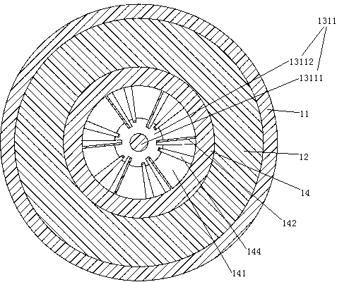
[0029] The motor body 1 includes an outer casing 11 , an outer stator 12 disposed on the outer casing 11 , and an inner rotor 14 located inside the outer stator 12 and supported on the outer casing 11 through a rotating shaft 13 . A bearing 15 is provided at the joint between the casing 11 and the rotating shaft 13 .

[0030] A plurality of air outlet channels 111 are provided on the right end of the casing 11 . The air outlet passages 111 are distributed along the circumference of the casing 11 . The outlet 1111 of the air outlet channel is dispo...


PUM


Abstract

The invention relates to a motor and provides a motor with brake and overload protection. The brake has an overload protection function and can avoid that a rotating shaft is broken off due to impact. The motor comprises a motor body, a brake mechanism and a hydraulic overload protector, wherein the motor body comprises an inner rotor and a rotating shaft; the rotating shaft comprises a driving shaft and a driven shaft which are coaxial; the hydraulic overload protector comprises an installation rack, a crankshaft and a pair of hydraulic cylinders; a communicating tube is arranged between two cylinder bodies in the pair of hydraulic cylinders; a bidirectional pressure valve is arranged on the communicating tube; the crankshaft comprises a main shaft and a connecting rod shaft; the main shaft is connected with the installation rack in a rotating manner; the driven shaft is fixedly connected with the main shaft; the connecting rod shaft is connected with the installation rack by an oil cylinder; and one end of the driving shaft is fixedly connected with the inner rotor and the other end thereof is fixedly connected with the installation rack. The invention solves the problem that the rotating shaft is possibly broken off in a braking process and the problem of poor overload protection action timeliness and reliability.

Description

technical field [0001] The invention relates to a motor, in particular to a motor with brake and overload protection. Background technique [0002] Motors are used on hoists or rolling gates. In order to stop the object at the desired position in time and accurately, a braking mechanism is provided on the motor so that the motor has a braking function. For example, a motor with braking function is disclosed in Chinese Patent No. 2004201500158, the date of authorization announcement is February 8, 2006, and the name is "motor with braking device". The motor in this patent document includes a motor body composed of a casing, a rotor and a stator, and a braking mechanism for braking the rotor. [0003] There are following deficiencies in the existing motor with brake: [0004] The rotor stops in an instant, so the inertial motion of the load has a large impact on the rotating shaft during the stopping process, which may easily cause the rotating shaft to break due to ins...

Claims


Application Information

Patent Timeline
Patent Type & Authority Applications(China)
IPC IPC(8): H02H7/085H02K5/00H02K9/04H02K5/20H02K7/102F16C3/02F16D1/06
Inventor 杨开生
Owner ZHEJIANG XINLI ELECTRIC APPLIANCE TECH CO LTD
Why Eureka
Eureka Blog
Learn More