Conveying and positioning mechanism for long tail clip wrench

A technology of positioning mechanism and long tail clip, applied in metal processing, metal processing equipment, manufacturing tools, etc., can solve the problems of low work efficiency, labor-intensive workers, finger damage, etc., and achieve the liberation of human labor, accurate positioning, orderly arrangement

Inactive Publication Date: 2013-02-13
宁波江北昌晟自动化科技有限公司
View PDF13 Cites 1 Cited by
  • Summary
  • Abstract
  • Description
  • Claims
  • Application Information

AI Technical Summary

Problems solved by technology

At present, the assembly of long tail clips is mainly manual, requiring a large number of workers to do simple repetitive work, which has low work efficiency, high labor intensity and easy to cause damage to the fingers of workers.

Method used


Image

  • Conveying and positioning mechanism for long tail clip wrench
  • Conveying and positioning mechanism for long tail clip wrench
  • Conveying and positioning mechanism for long tail clip wrench

Examples


Embodiment Construction

[0032] The present invention will be further described in detail below in conjunction with the accompanying drawings and embodiments.

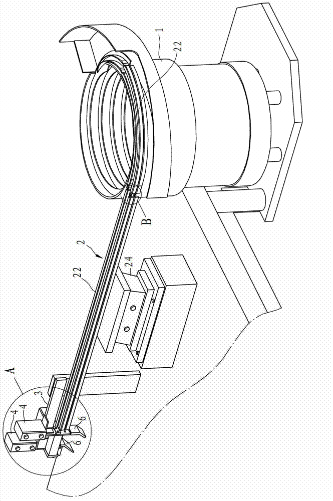
[0033] Such as image 3 , Figure 4 , Figure 5 and Figure 6 As shown, the delivery and positioning mechanism of the long tail clip wrench in this embodiment includes a vibrating plate 1, a delivery rail 2, a support 3, a baffle plate 7, a magnet 81, an output slot 6 and a vertical cylinder 4.

[0034] The vibrating plate 1 has a wrench output port, and the support seat 24 is provided under the conveying rail 2. The conveying rail 2 has a starting end and an end. The protruding rib 23 for hooking, the starting end 27 of the protruding rib is inclined upward and gradually raised to the level.

[0035] The support 24 is spaced apart from the vibrating plate 1. The baffle 7 is arranged on the support 24 and has a first side and a second side. There is a gap between the first side of the baffle and the end of the conveying rail 2 for a wrench...


PUM


Abstract

The invention relates to a conveying and positioning mechanism for a long tail clip wrench, which is characterized by comprising a vibration disc, a conveying rail, a support, a baffle, a magnet, an output slot and a vertical air cylinder, wherein the baffle is arranged on the support and is provided with a first side surface and a second side surface; a gap for the wrench to pass through is formed between the first side surface of the baffle and the tail end of the conveying rail; the magnet is arranged on the first side surface of the baffle; the output slot is formed in the bottom end of the baffle; and the vertical air cylinder is arranged on the support, and a push plate capable of vertically moving downwards to push the wrench into the output slot is arranged at the power output end of the vertical air cylinder. The conveying and positioning mechanism has the advantages that firstly, labors can be saved; and secondly, the wrench can be orderly arranged and accurately positioned to provide a good assembly foundation for subsequent assembly with a main body.

Description

technical field [0001] The invention relates to a long tail clamp assembly tool, in particular to a wrench conveying and positioning mechanism in the assembly tool. Background technique [0002] Existing long tail clip is used as a kind of stationery, and its application is very extensive, as figure 1 and figure 2 As shown, the long tail clamp 10 is composed of two parts: the main body (also known as: clamp body) 1a and the wrench (also known as: handle) 2a. The main body 1a is a bent metal sheet formed at one time, and the clamping force is provided by the deformation of the metal itself. A pair of hook grooves 11a are formed on both sides of the main body 1a. The wrench 2a is made of bent steel wire, usually two. Each wrench 2a has a hook portion 21a extending into the hook groove 11a at both ends. Because the manufacturing cost of the long tail clip is very low, and the individual profit is small, most enterprises produce it in large quantities. At present, the assemb...

Claims


Application Information

Patent Timeline
Patent Type & Authority Applications(China)
IPC IPC(8): B23P19/00
Inventor 毛毕伟俞浩杰
Owner 宁波江北昌晟自动化科技有限公司
Why Eureka
Try Eureka