Automatic grinding and polishing device for end surfaces of optical fibers and cables

An optical fiber cable, grinding and polishing technology, which is applied in grinding machines, grinding workpiece supports, grinding/polishing equipment, etc., can solve the problems of low grinding and polishing efficiency and unstable grinding and polishing quality.

Active Publication Date: 2013-02-13
NANJING CHUNHUI SCI & TECH IND
View PDF6 Cites 9 Cited by
  • Summary
  • Abstract
  • Description
  • Claims
  • Application Information

AI Technical Summary

Problems solved by technology

[0004] The technical problem to be solved by the present invention is to provide a device that can imitate human hands to apply force to the optical fiber cable end surface grinding and polishing fixture in view of the above-mentioned defects such as low grinding and polishing efficiency and unstable grinding and polishing quality of the automatic optical fiber cable end surface grinding device in the prior art. , High grinding and polishing efficiency, stable grinding and polishing quality, safe and reliable operation, and automatic grinding and polishing function of optical fiber cable end face automatic grinding and polishing device

Method used


Image

  • Automatic grinding and polishing device for end surfaces of optical fibers and cables
  • Automatic grinding and polishing device for end surfaces of optical fibers and cables
  • Automatic grinding and polishing device for end surfaces of optical fibers and cables

Examples


Embodiment Construction

[0026] In order to make the object, technical solution and advantages of the present invention clearer, the present invention will be further described in detail below in conjunction with the accompanying drawings and embodiments. It should be understood that the specific embodiments described here are only used to explain the present invention, not to limit the present invention.

[0027] Preferred embodiments of the present invention are as follows:

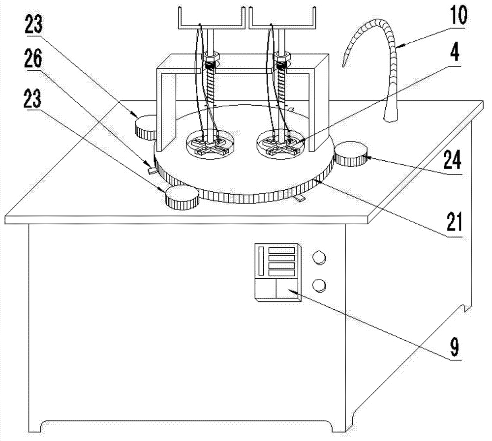
[0028] Such as figure 1 As shown, the optical fiber cable end face automatic grinding and polishing device described in this embodiment includes a chassis, a grinding and polishing assembly, and an electric control device 9; the grinding and polishing assembly is connected to the chassis, and the electric control device 9 is fixed on the chassis, and the chassis is also equipped with Automatic water adding device 10.

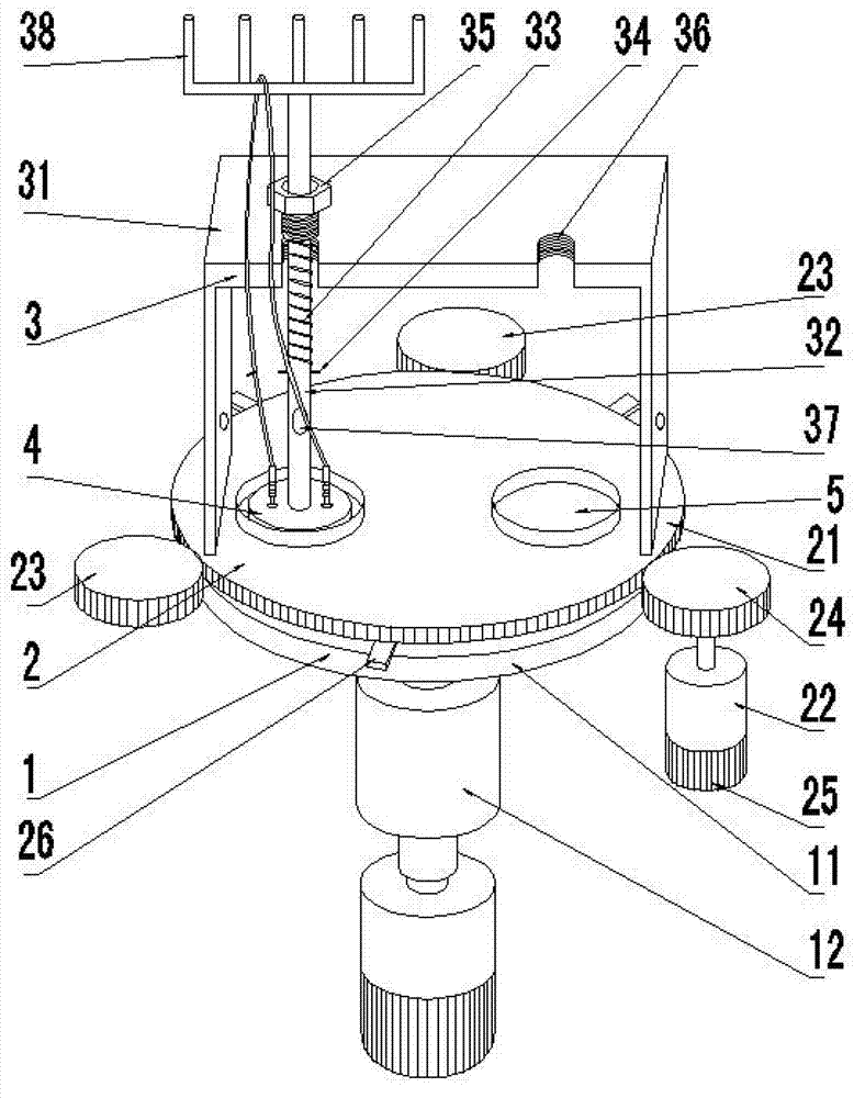
[0029] Such as figure 2 As shown, the grinding and polishing assembly includes a plane grinding and polishin...


PUM


Abstract

The invention discloses an automatic grinding and polishing device for end surfaces of optical fibers and cables. The automatic grinding and polishing device comprises a machine case, a grinding and polishing assembly and an electric control unit. The grinding and polishing assembly comprises a plane grinding and polishing mechanism, an emulational hand assembly, a grinding and polishing clamp and an elastic boosting device, wherein the emulational hand assembly comprises a working disc, a driving wheel, a transmission motor, a driven wheel and a working disc rotating booster; the driven wheel and the driving wheel are in external meshing with the working disc; the elastic boosting device comprises a grinding and polishing clamp connection rod and a working disc gantry base; the grinding and polishing clamp connection rod is connected with the working disc gantry base; the working disc gantry base is arranged on the working disc, the grinding and polishing clamp connection rod is connected with the grinding and polishing clamp, and the grinding and polishing clamp is assembled in a working hole; and the working disc rotating booster is respectively connected with the working disc and the plane grinding and polishing disc. The automatic grinding and polishing device for end surfaces of the optical fibers and cables can perform automatic grinding and polishing, can stimulate human hands to exert force on the grinding and polishing clamp of the optical fibers and cables, and is high in grinding and polishing efficiency, stable in grinding and polishing quality and safe and reliable to operate.

Description

technical field [0001] The invention relates to a plane grinding and polishing device, in particular to an automatic grinding and polishing device for the end face of an optical fiber cable. Background technique [0002] At present, the grinding and polishing of the end face of optical fiber cable is mainly manual classical grinding and polishing. The main feature of manual classical grinding and polishing is to fix the coupling end of the optical fiber cable on the grinding and polishing fixture, and control the grinding and polishing by manual pressure and different trajectory movements. The grinding force between the coupling end of the optical fiber cable on the fixture and the grinding and polishing disc is controlled by the hand feel to control the force balance of the grinding and polishing fixture. However, manual grinding and polishing is not only inefficient, but also unstable and highly dependent on the quality of optical fiber cable grinding and polishing, and is...

Claims


Application Information

Patent Timeline
Patent Type & Authority Applications(China)
IPC IPC(8): B24B7/16B24B41/06
Inventor 徐明泉朱云青潘维超黄晓云章均
Owner NANJING CHUNHUI SCI & TECH IND
Why Eureka
Try Eureka