Concrete member molding machine

A molding machine and concrete technology, which is applied in the field of water collection well grate molding machine and concrete inspection manhole cover, can solve the problems of backward production technology, low production efficiency, and low degree of mechanization, so as to improve production efficiency, reduce work intensity, and liberate productivity Effect

Active Publication Date: 2013-02-13
保定市华光市政建材有限公司
View PDF8 Cites 11 Cited by
  • Summary
  • Abstract
  • Description
  • Claims
  • Application Information

AI Technical Summary

Problems solved by technology

[0004] In order to solve at least one of the technical problems in the above-mentioned prior art, such as backward production technology of concrete inspection manhole covers, water collection well grates, etc., low degree of mechanization, high labor intensity of workers, difficult control of product quality, low production efficiency, etc., the present invention provides a A concrete component forming machine can effectively overcome the above-mentioned defects of the prior art

Method used


Image

  • Concrete member molding machine
  • Concrete member molding machine
  • Concrete member molding machine

Examples


Embodiment 1

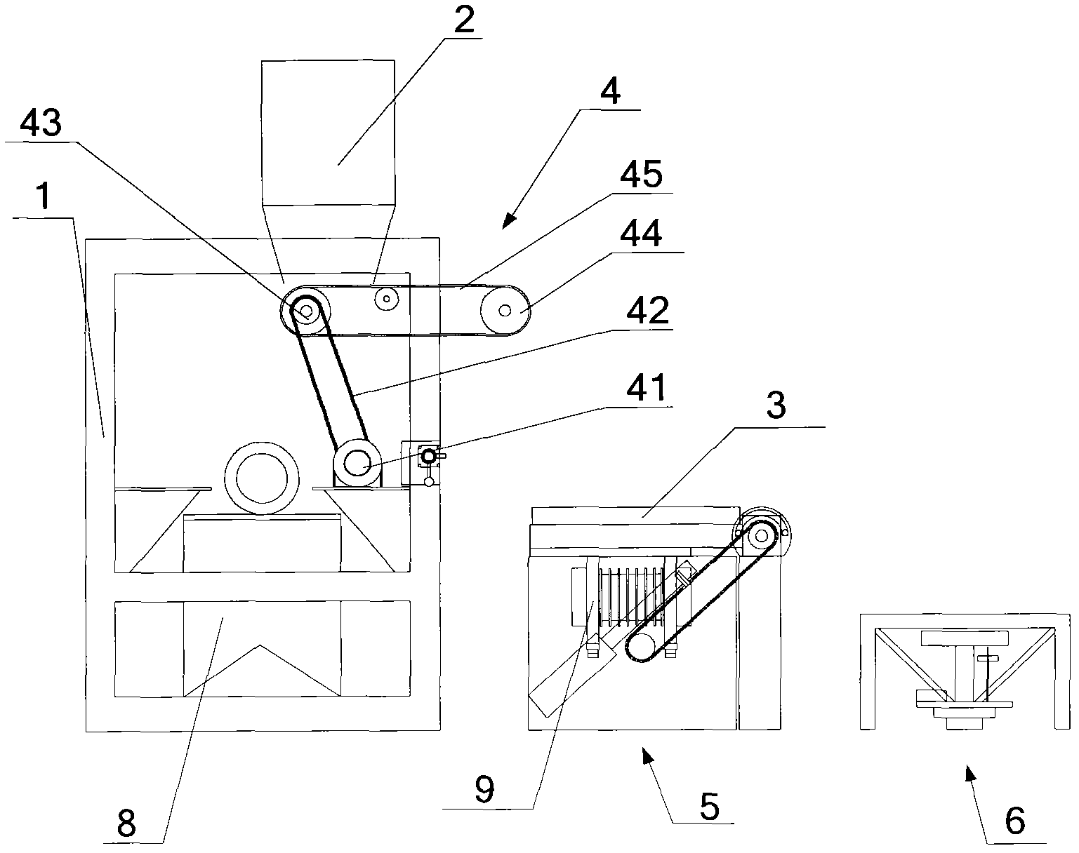
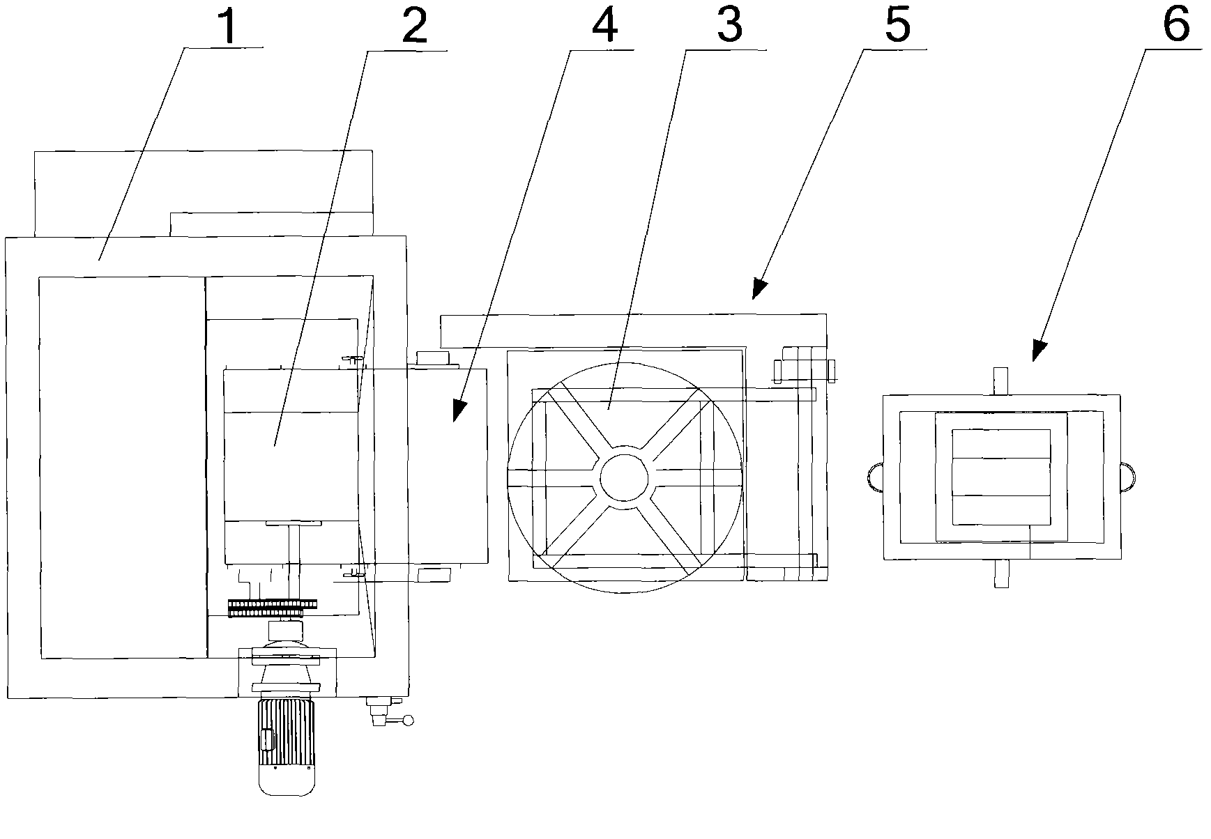
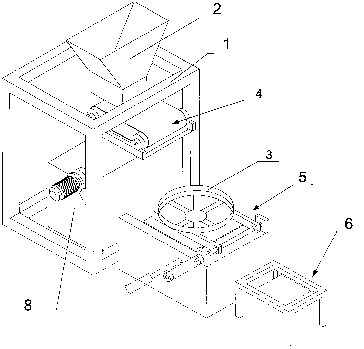
[0042] figure 1 It shows a schematic structural view of an embodiment of the concrete forming machine according to the present invention; figure 2 show figure 1 A schematic top view of the structure shown; image 3 show figure 1 A three-dimensional schematic diagram of the structure shown; Figure 4 It shows a schematic structural view of an embodiment of the rack according to the present invention; Figure 5shows a schematic structural view of an embodiment of the turning mechanism according to the present invention; Image 6 It shows a schematic structural view of an embodiment of the splicing machine according to the present invention; Figure 7 show Image 6 The three-dimensional schematic diagram of the bamboo plywood on the structure shown in ; Figure 8 A schematic structural view of an embodiment of the vibrating forming device according to the present invention is shown; Figure 9 shows the basis Figure 8 Schematic diagram of the front view of the structure...

Embodiment 2

[0061] Figure 11 It shows a schematic structural view of another embodiment of the concrete component molding machine according to the present invention; Figure 12 shows the basis Figure 11 A schematic top view of the structure shown; Figure 13 A schematic structural view of an embodiment of the palletizer according to the present invention is shown; Figure 14 show Figure 13 A schematic front view of the structure shown in .

[0062] like Figure 11 to Figure 16 As shown, this embodiment is basically the same as Embodiment 1, the difference is that:

[0063] It also includes a stacker 7 arranged on one side of the plate receiving machine 6, and the stacker 7 includes a stacker frame 71, a mobile frame 72, a slider 73, a slider lifting device and a mobile frame walking device, so The slider 73 is installed on the moving frame 72, and can move up and down along the moving frame 72 under the action of the slider lifting device, and the moving frame 72 is installed on ...

Embodiment 3

[0069] This embodiment is basically the same as the second embodiment, the difference is that: the lifting device of the slider and the traveling device of the mobile frame of the palletizer both adopt hydraulic cylinders.

[0070] like Figure 18 , Figure 19As shown, the stacker 7 includes a stacker frame 71, a mobile frame 72 slider 73, the slider lifting device can also be a slider lifting oil 76, and the mobile frame walking device can also be a mobile frame walking Oil cylinder 77, described moving frame 72 is installed on the described stacker frame 71, and one end of described stacker frame 71 is fixed on the described frame 1, and one end of described moving frame walking oil cylinder 77 is fixed on the described On the frame 1, the other end is fixed on the moving frame 72, and the moving frame 72 can move linearly along the chute 711 of the stacker frame 71 under the action of the moving frame walking cylinder 77; Slide block lift cylinder 76 and slide block 73 ar...


PUM


Abstract

The invention provides a concrete member molding machine, which comprises a frame (1), a material feeding device (2), a mold (3), a material distributor (4), a turnover mechanism (5), a plate receiving machine (6) and a vibrating and molding device (9), wherein the material feeding device (2) is arranged above the frame (1); the material distributor (4) is arranged below the material feeding device (2); the mold (3) is arranged below the material distributor (4); the vibrating and molding device (9) is arranged below the mold (3); the mold (3) is mounted on the turnover mechanism (5); and the plate receiving machine (6) is arranged on one side of the turnover mechanism (5). Through the adoption of the concrete member molding machine provided by the invention, feeding, distributing, vibrating and molding, turnover, conveying as well as stacking of concrete can be automatically finished, labor intensities of workers are reduced and the production efficiency of an enterprise is increased.

Description

technical field [0001] The invention relates to the field of forming concrete components, and more specifically relates to a forming machine for a concrete inspection well cover and a water collection well grate. Background technique [0002] At present, in the production process of concrete inspection well covers and water collection well grates in China, manual mixing, manual distributing, manual turning, manual handling and stacking of semi-finished products are generally used, and the degree of mechanization is low, which makes the labor intensity of workers extremely high and the product quality is difficult to control. , Low production efficiency. [0003] Therefore, there is a need for a fully automatic or semi-automatic concrete forming machine, which can automatically complete concrete mixing, distributing, vibrating, turning, transporting and stacking, which greatly liberates productivity and improves the production efficiency of enterprises. Contents of the inve...

Claims


Application Information

Patent Timeline
Patent Type & Authority Applications(China)
IPC IPC(8): B28B15/00B28B13/02B28B17/00B28B1/087
Inventor 郑军张继学张学永郑进松
Owner 保定市华光市政建材有限公司
Why Eureka
Try Eureka