
Locomotive distribution valve and working method thereof

A technology for distributing valves and locomotives, which is applied to vehicle parts, control valves, air release valves, brake components, etc. It can solve the problems of easy rusting of valve bodies, large structural volume, and unguaranteed safety of train running, etc., and achieves The effect of reducing the frequency of use

Active Publication Date: 2013-02-13
MEISHAN CRRC BRAKE SCI & TECH CO LTD
View PDF5 Cites 22 Cited by
  • Summary
  • Abstract
  • Description
  • Claims
  • Application Information

AI Technical Summary

Problems solved by technology

[0002] At present, in the locomotive electro-pneumatic brake, the existing locomotive distribution valve needs a safety valve to control the pressure of the brake cylinder during emergency braking, thereby increasing the frequency of use of the safety valve and making the train run safely. There is no guarantee, and after a long time of use of the existing distribution valve, the valve body is easily corroded, and the inner cavity of the valve is easy to rust, which affects its service life. The structure is large in size and the maintenance cost is high

Method used


Image

  • Locomotive distribution valve and working method thereof
  • Locomotive distribution valve and working method thereof
  • Locomotive distribution valve and working method thereof

Examples


Embodiment Construction

[0033] Below in conjunction with accompanying drawing, the present invention is described in detail.

[0034] In order to make the object, technical solution and advantages of the present invention clearer, the present invention will be further described in detail below in conjunction with the accompanying drawings and embodiments. It should be understood that the specific embodiments described here are only used to explain the present invention, not to limit the present invention.

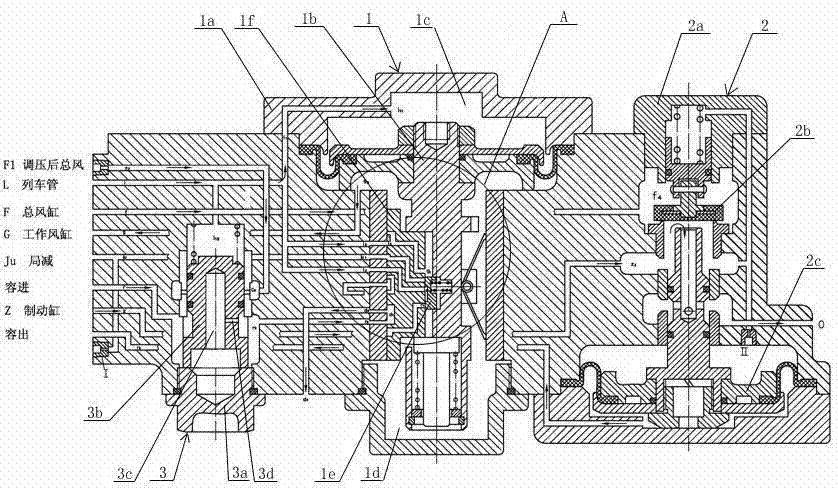
[0035] Such as figure 1 As shown, a locomotive distribution valve is composed of an action valve 1, a balance valve 2 and an emergency boost valve 3, and the action valve 1, the balance valve 2 and the emergency boost valve 3 pass through the The gas path connection plate is connected, and the emergency booster valve is combined with the gas path connection plate; the action valve, balance valve, and emergency booster valve can be disassembled separately.

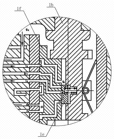
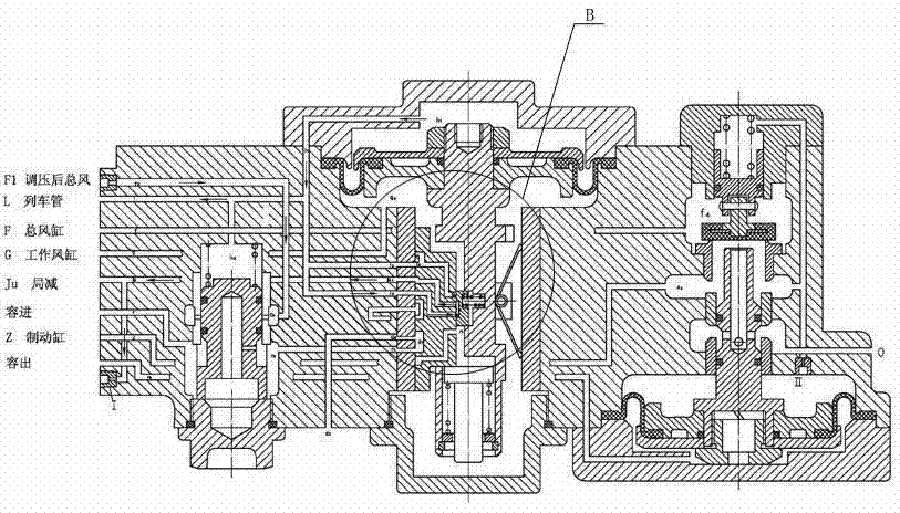
[0036] Wherein, the action valve 1 inc...


PUM


Abstract

The invention discloses a locomotive aluminum-alloy distribution valve applicable for an electrically-controlled brake of a locomotive, and a working method of the locomotive aluminum-alloy distribution valve. The distribution valve consists of an operating valve, a balance valve and an emergency pressure-increasing valve, wherein the operating valve, the balance valve and the emergency pressure-increasing valve are communicated with one another by a gas circuit connecting board arranged on the emergency pressure-increasing valve. The operating valve, the balance valve and the emergency pressure-increasing valve are combined together and then are arranged on a gas circuit board used for the existing locomotive; a brake cylinder of the locomotive is inflated and exhausted according to the pressure change movement of a train pipe, so that the locomotive is braked, pressurized and relieved. In the common brake, the emergency pressure-increasing valve is closed; when a train is in an emergency brake, the emergency pressure-increasing valve is opened, and pressure-regulated main air flows into a volume room through an opened valve port, so as to exert the effect of pressurization of the volume room; and the brake cylinder can obtain the controllable pressure larger than the common braking pressure due to the action of the balance valve, so as to guarantee the driving safety of the train.

Description

technical field [0001] The invention relates to an aluminum alloy locomotive distribution valve suitable for an electropneumatic brake of a locomotive and a working method thereof. Background technique [0002] At present, in the locomotive electro-pneumatic brake, the existing locomotive distribution valve needs a safety valve to control the pressure of the brake cylinder during emergency braking, thereby increasing the frequency of use of the safety valve and making the train run safely. There is no guarantee, and after the existing dispensing valve is used for a long time, the valve body is easily corroded, and the inner cavity of the valve is easy to rust, which affects its service life. The structure is relatively large and the maintenance cost is relatively high. Contents of the invention [0003] The object of the present invention is to solve the above-mentioned problems and provide an aluminum alloy locomotive distributing valve with high corrosion resistance, com...

Claims


Application Information

Patent Timeline
Patent Type & Authority Applications(China)
IPC IPC(8): B60T15/02
Inventor 刘亚梅朱宇杜霞申燕飞黄军张俊英
Owner MEISHAN CRRC BRAKE SCI & TECH CO LTD
Learn More