Eureka AIR delivers breakthrough ideas for toughest innovation challenges, trusted by R&D personnel around the world.

Hydraulic retarder with pressure power generation device and control method thereof

A technology of hydraulic retarder and pressure power generation, which is applied to piezoelectric effect/electrostrictive or magnetostrictive motors, generators/motors, liquid resistance brakes, etc. Energy has not been recycled and other problems, to achieve the effect of saving energy

Active Publication Date: 2013-02-13
JIANGSU UNIV
View PDF4 Cites 8 Cited by
  • Summary
  • Abstract
  • Description
  • Claims
  • Application Information

AI Technical Summary

Problems solved by technology

[0007] The purpose of the present invention is to solve the problem that the braking energy of the automobile is not recycled when the hydraulic retarder is working, and to solve the problem that the hydraulic retarder converts the kinetic energy of the automobile into liquid heat energy and causes the cooling system to be overloaded , At the same time, in order to solve the problem of independent heat dissipation of the hydraulic retarder, a hydraulic retarder with a pressure power generation device and its control method are provided, which makes the arrangement of the hydraulic retarder on the car more convenient; can improve the hydraulic retarder The safety of the hydraulic retarder ensures that the hydraulic retarder can still work after the engine stops working

Method used


Image

  • Hydraulic retarder with pressure power generation device and control method thereof
  • Hydraulic retarder with pressure power generation device and control method thereof
  • Hydraulic retarder with pressure power generation device and control method thereof

Examples


Embodiment Construction

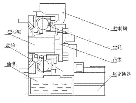
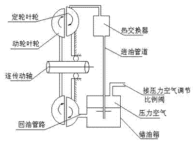
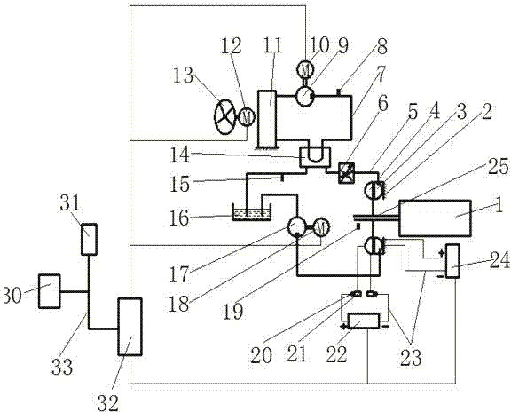
[0025] image 3 As shown, the structure of the hydraulic retarder with pressure generating device of the present invention includes a retarder body, a heat dissipation system, a pressure generating device, an electronic control system and other parts. The hydraulic retarder can be arranged at the output end of the transmission, the input end of the transmission and the input end of the rear axle as required. Here, the arrangement at the output end of the transmission is taken as an example for description.

[0026] The retarder body includes a moving wheel 3, a fixed wheel 4, a retarder housing 2, an oil pump 17, an oil pump driving motor 18, a working fluid storage tank 16, a throttle valve 6, and the like. The moving wheel 3 and the fixed wheel 4 are coaxially opposed with a gap, and the gap between the moving wheel 3 and the fixed wheel 4 forms a sealed working chamber. The oil inlet and liquid outlet are opened on the working chamber, and the fixed wheel 4 is fixed on...


PUM


Abstract

The invention discloses an automobile hydraulic retarder with a pressure power generation device and a control method thereof. A piezoelectric material sheet is fixedly arranged on pressure surface of each impeller blade of a moving wheel and a fixed wheel, anodes and cathodes of the piezoelectric material sheets on adjacent impeller blades of the moving wheel and the fixed wheel are in sequential serial connection to form a moving wheel pressure power generation module and a fixed wheel pressure power generation module, the fixed wheel pressure power generation module is connected with a fixed wheel capacitor, the moving wheel pressure power generation module is connected with a moving wheel capacitor through a copper ring and an electric brush, the fixed wheel capacitor and the moving wheel capacitor are connected with a storage battery, one end of an oil pump is connected with an oil inlet of the working cavity, the other end of the oil pump is connected with a working liquid storage tank which is connected with a heat exchanger, the heat exchange is connected with the oil inlet of the working cavity through a throttle valve, by means of the pressure power generation devices, during braking, the liquid kinetic energy which impacts the moving wheel and the fixed wheel is converted into electric energy to be stored in the storage battery, the braking energy can be effectively recycled, an independent heat dissipation system is arranged, and the continuous braking can be performed under the condition that an engine is shut down.

Description

technical field [0001] The invention relates to the energy-saving technology of an automobile hydraulic retarder, in particular to a hydraulic retarder with a pressure generating device and a control method thereof. Background technique [0002] At present, mature hydraulic retarder products are represented by Voith (Voith) R133-2 type, Voith (Voith) R133-2 type hydraulic retarder such as figure 1 As shown, it consists of a moving wheel, a fixed wheel working chamber, an input shaft, a heat exchanger, an oil storage tank and a housing. For automatic transmission vehicles equipped with hydraulic torque converters, the original transmission system has been equipped with components such as oil storage tanks, oil pumps and radiators. Retarders cost less. When the retarder works, if figure 2 As shown, the compressed air enters the oil storage tank through the solenoid valve, and the oil in the oil storage tank is pressed into the working cavity of the retarder through the oi...

Claims


Application Information

Patent Timeline
Patent Type & Authority Applications(China)
IPC IPC(8): F16D57/02H02N2/18
Inventor 何仁胡东海
Owner JIANGSU UNIV
Why Eureka
Eureka Blog
Learn More