Anti-drop structure for regulating valve bushing

A technology of anti-dropping structure and regulating valve, applied in the direction of valve shell structure, lift valve, valve details, etc., can solve the problems of corrosion and falling off of hexagon socket flat-end set screws, affecting valve adjustment and sealing performance, and stopping the whole set of devices, etc. Hazardous machining operations, quick and reliable assembly, reduced dimensional tolerance requirements

Inactive Publication Date: 2013-02-13
WUXI SMART AUTO CONTROL ENG CO LTD
View PDF11 Cites 2 Cited by
  • Summary
  • Abstract
  • Description
  • Claims
  • Application Information

AI Technical Summary

Problems solved by technology

There is no problem with this structure under normal conditions, but the presence of strong corrosive media inside the control valve causes the hexagon socket flat-end set screw to suffer from corrosion and fall off, eventually causing the bush to fall off, affecting the valve’s adjustment and sealing performance, and even causing the valve to be stuck. , so that the valve fails, and then the whole device is shut down, resulting in huge economic losses

Method used


Image

  • Anti-drop structure for regulating valve bushing
  • Anti-drop structure for regulating valve bushing
  • Anti-drop structure for regulating valve bushing

Examples


Embodiment 1

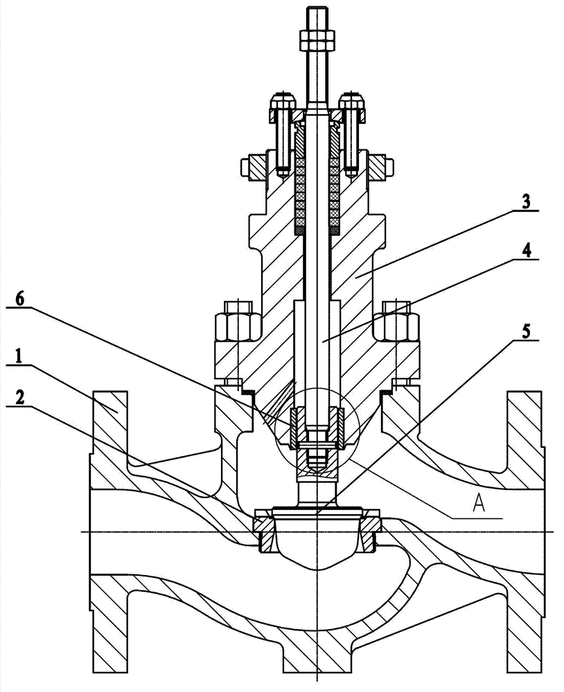
[0022] Such as figure 1 , 2 , 3 shows: the control valve bushing anti-off structure, including valve body 1, valve seat 2, valve cover 3, valve stem 4, valve core 5 and bushing 6, valve seat 2 is fixed in valve body 1, A bonnet 3 is fixed on the valve body 1, a valve stem 4 is inserted into the bonnet 3 for sliding sealing, and a valve core 5 is fixed at the bottom end of the valve stem 4,

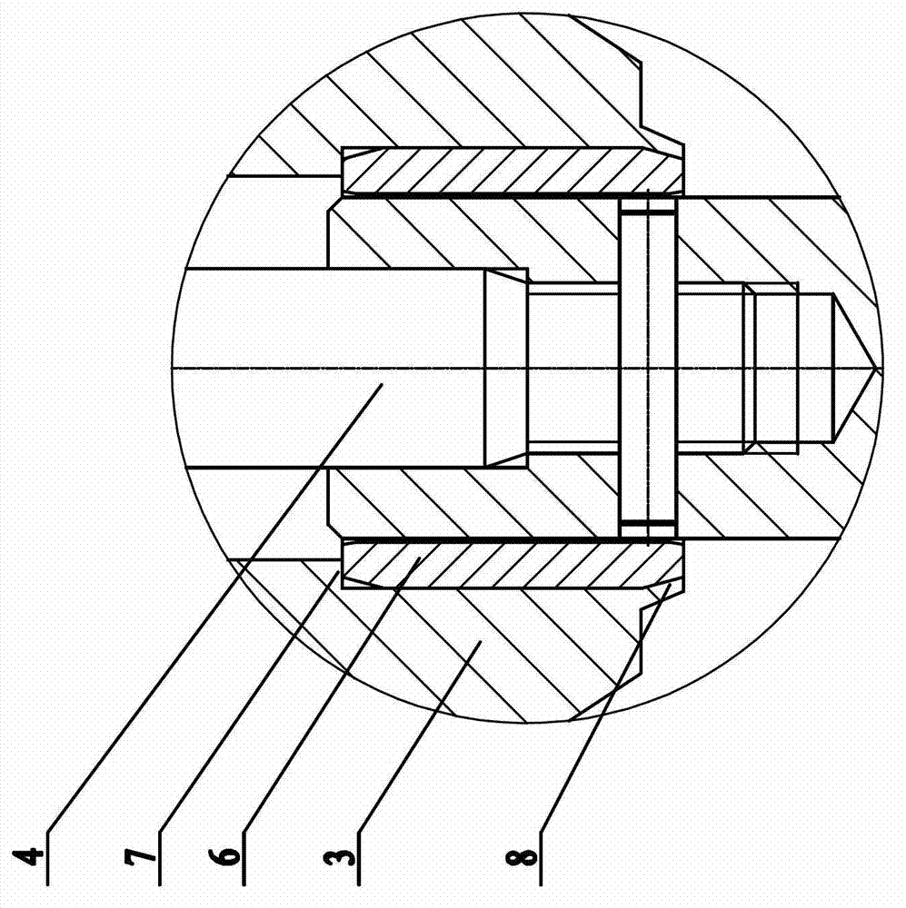
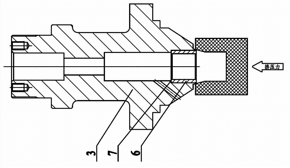
[0023] One end surface of the bush 6 is in contact with the limiting step 7, the outer edge of the other end of the bush 6 is provided with a limiting outer cone, and the other end of the bushing 6 is in contact with the limiting inner cone of the extrusion turning 8. surface contact.

[0024] The bottom end of the valve cover 3 is provided with the extruding flange 8, the extruding flange 8 has a limiting inner cone surface, and the limiting inner conical surface of the extruding flange 8 is in contact with the outer edge of the bottom end of the bushing 6. The limiting outer cone surf...

Embodiment 2

[0028] Such as Figure 4 , 5 , 6: the control valve bushing anti-off structure, including valve body 1, valve seat 2, valve cover 3, valve stem 4, valve core 5 and bushing 6, valve seat 2 is fixed in valve body 1, A valve cover 3 is fixed on the valve body 1, and a valve stem 4 is inserted into the valve cover 3 in a sliding and sealing manner, and a valve core 5 is fixed at the bottom end of the valve stem 4. The steps 7 offset each other, and the outer edge of the other end of the bush 6 is provided with a limit outer cone surface, and the other end of the bush 6 is in contact with the limit inner cone surface of the extruded flange 8 .

[0029] A bushing seat 9 is also provided under the valve cover 3, and the bottom end of the bushing seat 9 is provided with the limiting step 7, and the bottom end surface of the bushing 6 is offset against the limiting step 7, and the bushing seat 9 The top end portion is provided with the extrusion flanging 8, the extrusion flange 8 has...


PUM


Abstract

The invention relates to an anti-drop structure for a regulating valve bushing, which comprises a valve body, a valve seat, a valve cover, a valve rod, a valve core and a bushing, wherein the valve seat is fixed in the valve body, the valve cover is fixed on the valve body, the valve rod is spliced in the valve cover in a sliding and sealing manner, the valve core is fixed at the bottom end part of the valve rod, an end face of the bushing pushes against limiting steps, a limiting outer conical surface is arranged at the outer side edge of the other end part of the bushing, and the other end part of the bushing is contacted with a limiting inner conical surface of an extruding flange. With the adoption of the structure, tools such as a drilling bit and a screw tap are not required during the assembly course, as the drilling bit and the screw tap are easy to break when in use to cause work injuries, dangerous processing procedures are reduced, the requirement for the dimensional tolerances of the bushing and a matching surface of the bushing is lowered, the assembly is faster and more reliable, the assembly efficiency is improved, the number of the location steps is increased, the drop of the bushing is effectively prevented, the reliability of a product is improved, the service life of the product is prolonged, and the significant economic benefit is achieved.

Description

technical field [0001] The invention relates to a valve structure, in particular to an anti-off structure for a bushing of a regulating valve. Background technique [0002] With the development of the economy and the continuous improvement of the level of industrial automation control, the requirements for the adjustment accuracy and reliability of the control valve, an important actuator in the process control, are also continuously improved. At present, the bushing used in the control valve usually uses two conventional structures: [0003] 1. The bushing is interference fit to the upper cover and the bushing seat for guidance, and there is no positioning step. There is no problem with this structure under normal conditions, but due to the existence of high-temperature medium and strong corrosive medium inside the regulating valve, the matching surfaces of the upper cover, the bushing seat and the bushing will expand and corrode, which will eventually cause the bushing to...

Claims


Application Information

Patent Timeline
Patent Type & Authority Applications(China)
IPC IPC(8): F16K1/00F16K1/32F16K27/12
Inventor 陈彦王汪洋盛子烨张程
Owner WUXI SMART AUTO CONTROL ENG CO LTD
Why Eureka
Try Eureka