
Intelligent diagnosis method for corrosion failure point of transformer substation grounding grid

A substation grounding grid, intelligent diagnosis technology, applied in fault location, measurement of electricity, measurement of electrical variables and other directions, can solve the problems of inaccurate calculation results, inaccurate positioning of electric potential distribution, inability to calculate by PC, and achieve the goal of suppressing electromagnetic interference. Effect

Active Publication Date: 2013-02-13
HUZHOU ELECTRIC POWER ADMINISTATION ZHEJIANG PROV +1
View PDF5 Cites 28 Cited by
  • Summary
  • Abstract
  • Description
  • Claims
  • Application Information

AI Technical Summary

Problems solved by technology

It can not only avoid the problem of inaccurate positioning only through the potential distribution, but also avoid the problem that the PC cannot be calculated or the calculation result is inaccurate because the grounding grid is too large. The method is simple, the diagnosis efficiency is high, and the engineering practicability is strong.

Method used


Image

  • Intelligent diagnosis method for corrosion failure point of transformer substation grounding grid
  • Intelligent diagnosis method for corrosion failure point of transformer substation grounding grid
  • Intelligent diagnosis method for corrosion failure point of transformer substation grounding grid

Examples


Embodiment Construction

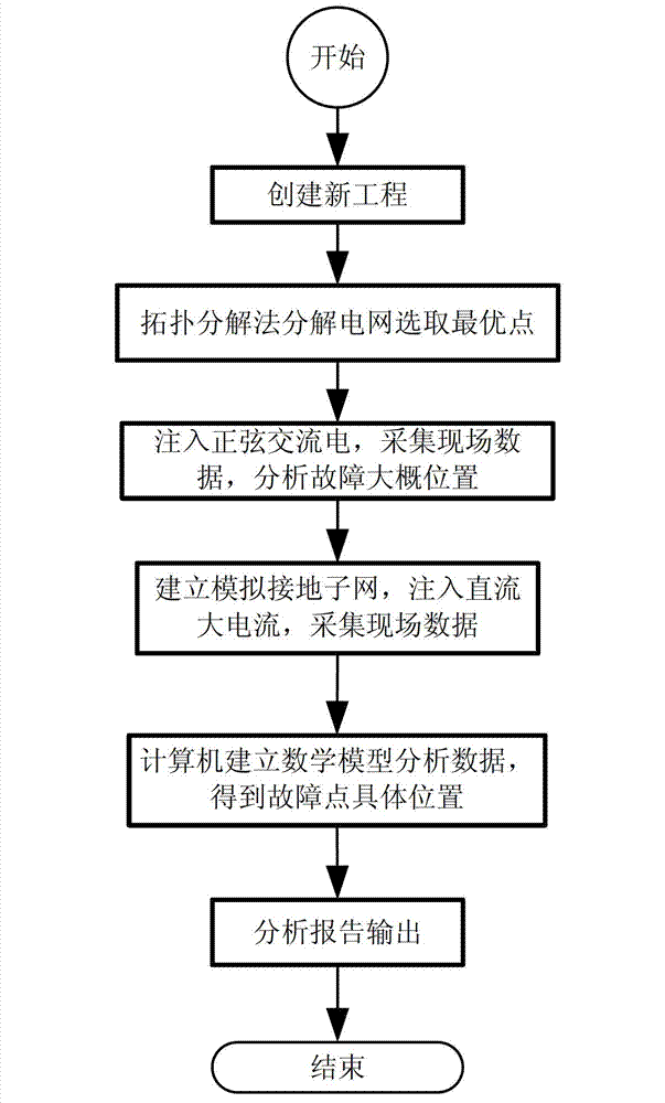
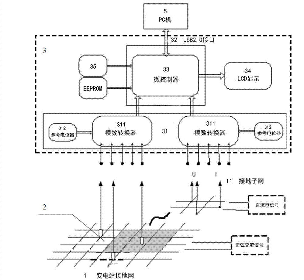
[0018] refer to figure 1 and figure 2 , the preferred embodiment of the intelligent diagnosis method for substation grounding grid corrosion fault points of the present invention includes the steps: 1) analyzing the structural model of the substation grounding grid 1 through the terminal processor 5 of the diagnosis system, applying the topology decomposition method to decompose the substation grounding grid 1 and Select the best point; 2) Inject a sinusoidal AC signal into the substation grounding grid 1, and collect the potential signal by the AC signal acquisition sensor 2 and transmit it to the AC and DC signal acquisition system 3; 3) Transmit the potential signal to the The terminal processor 5 calculates and displays it to a liquid crystal display 34; 4) The terminal processor 5 calculates the approximate area where the corrosion fault point is located according to the potential signal distribution, and builds a structural model of a small grounding subnet 11 in this a...


PUM


Abstract

The invention provides an intelligent diagnosis method for the corrosion failure point of a transformer substation grounding grid. The method comprises the following steps of: firstly, inputting a transformer substation grounding grid model into a computer, on the premise that the structure of the transformer substation grounding grid is analyzed, decomposing the transformer substation grounding grid and selecting an optimum point by a topology decomposition method, acquiring an electric potential signal and transmitting to an alternating current / direct current signal acquiring system by a preset sensor due to an injected sine alternating current single, transmitting the signal to the computer to be computed and displayed on a liquid crystal display by a microcontroller, computing the probable position in which the corrosion failure point is arranged by the computer according to the electric potential distribution, building a mini type grounding subgrid model, injecting a direct current large current signal into the mini type grounding subgrid, acquiring by a controller to acquire the node voltage and the current valve of the grounding grid at the time, and transmitting the acquired data to the computer to build mathematical model computation to finally obtain the specific position of the corrosion failure point.

Description

technical field [0001] The method relates to a distribution substation signal acquisition analysis and transmission technology, more specifically, the invention relates to an intelligent diagnosis method for corrosion fault points of a substation grounding grid. technical background [0002] With the development of modern large power grids in the direction of ultra-high voltage, large capacity and long distance, the requirements for the safety, stability and economic operation of the power system are getting higher and higher. In order to ensure the safe and stable operation of the power grid and improve the reliability of power supply, there must be a Good substation grounding device. [0003] The reason is that the grounding grid is a hidden facility buried deep underground in the power system. The main technical problems exposed on site are corrosion of the grounding grid, small cross-section of the grounding down-conductor, and poor connection between grounding bodies. T...

Claims


Application Information

Patent Timeline
IPC IPC(8): G01R31/00G01R31/08
CPCY04S10/522Y04S10/52
Inventor 朱雪松邬欣杨莉萍陈美荣吴国强王炜
Owner HUZHOU ELECTRIC POWER ADMINISTATION ZHEJIANG PROV
Learn More