Full fiber optic current sensor and current closed loop feedback correction method

A current sensor, fiber optic current technology, applied in the direction of instruments, adjusting electrical variables, control/regulating systems, etc., can solve the problems of unstable performance, laser wavelength drift, unstable sensor performance, etc., to achieve the effect of enhanced anti-interference

Active Publication Date: 2013-02-13
上海康阔光智能技术有限公司
View PDF11 Cites 6 Cited by
  • Summary
  • Abstract
  • Description
  • Claims
  • Application Information

AI Technical Summary

Problems solved by technology

Although various research units have made great efforts, there are still considerable problems in the stability of the photoelectric signal processing unit, especially in low temperature conditions, the problem is still quite serious. Difficult to within plus or minus two thousandths, let alone for the entire sensor
The instability of sensor performance is mainly caused by factors such as long-term performance deterioration of various optical devices, unstable performance under high and low temperature conditions, and laser wavelength drift. Although measures such as heat preservation or temperature control can be used, they still cannot be effectively suppressed. Uncertainty in the above performance

Method used


Image

  • Full fiber optic current sensor and current closed loop feedback correction method
  • Full fiber optic current sensor and current closed loop feedback correction method
  • Full fiber optic current sensor and current closed loop feedback correction method

Examples


Embodiment Construction

[0025] The present invention will be further described in detail below in conjunction with the accompanying drawings and specific embodiments.

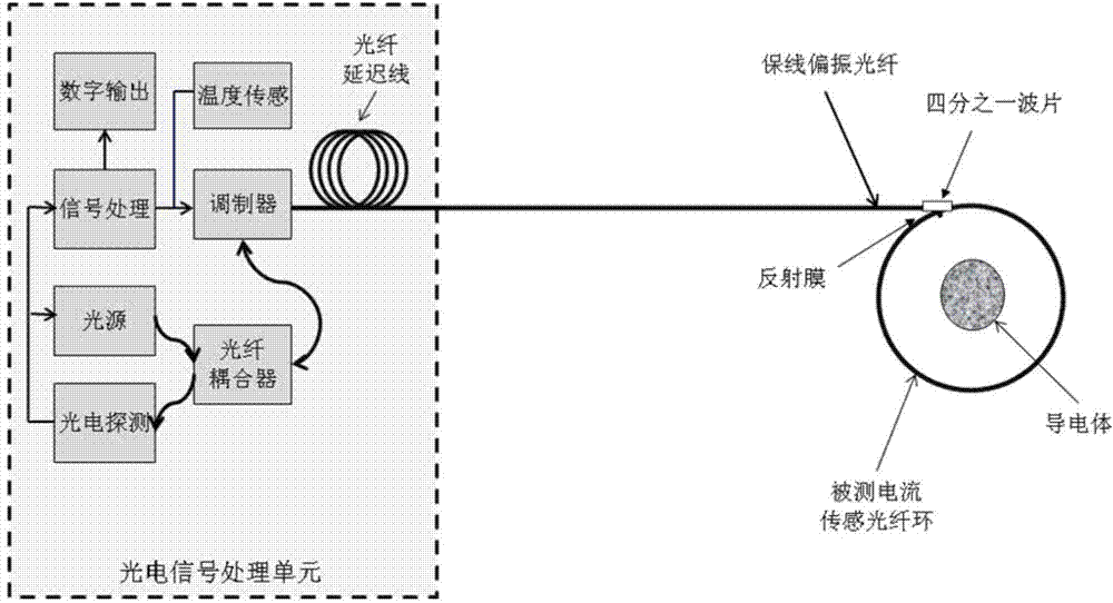
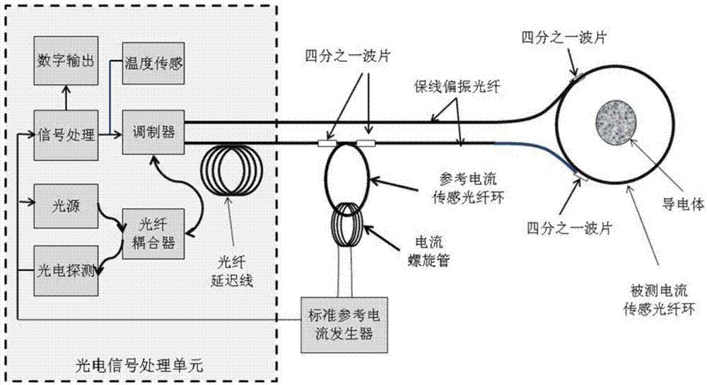
[0026] The present invention provides an all-optical fiber current sensor, which includes a photoelectric signal processing unit, including two sensing optical fiber rings connected in series with the optical fiber delay line in the photoelectric signal processing unit, wherein one sensing optical fiber ring is a reference current sensing optical fiber ring , the other is the measured current sensing optical fiber ring, the reference current sensing optical fiber ring is connected in series between the optical fiber delay line and the measured current sensing optical fiber ring, and its beginning end is the same as the end of the optical fiber delay line of the photoelectric signal processing unit Fusion splicing, the end is fused with the beginning of the measured current sensing optical fiber ring. A current wire is wound around the...


PUM


Abstract

The invention discloses a full fiber optic current sensor and a current closed loop feedback correction method. The full fiber optic current sensor comprises an optoelectronic signal processing unit and two sensor fiber rings which are connected with the optoelectronic signal processing unit in series and located at the back of an optical fiber delay line, one of the sensor fiber ring is a reference current sensor fiber ring, the other sensor fiber ring is a measured current sensor fiber ring, the reference current sensor fiber ring is connected between the optical fiber delay line and the measured current sensor fiber ring in series, a current wire is wound on the reference current sensor fiber ring, two ends of the current wire are connected onto a standard reference current generator, and the standard reference current generator is in communication connection with the optoelectronic signal processing unit. The full fiber optic current sensor and the current closed loop feedback correction method can compensate measuring errors of the system caused by long-term ageing and high temperature changes.

Description

technical field [0001] The invention relates to an intelligent current sensor or a transformer of a power transmission system, and specifically belongs to an all-optical fiber current sensor and a current closed-loop feedback correction method for precise measurement of current and dynamic monitoring of power grid safety. Background technique [0002] The fiber optic current sensor is one of the core equipment of the future smart grid. Since the early 1980s to the present, many universities, research institutes and related companies at home and abroad have invested a lot of manpower, material and financial resources in its research and development, but so far , has not really formed a large-scale promotion and application, and the core problem is that its accuracy or long-term stability cannot meet or fail to meet the standards of the power industry. The basic principle of the fiber optic current sensor is to use the Faraday effect, and its specific technology is based on th...

Claims


Application Information

Patent Timeline
Patent Type & Authority Applications(China)
IPC IPC(8): G05F1/565
Inventor 黄勇
Owner 上海康阔光智能技术有限公司
Why Eureka
Try Eureka