

Chip dynamic voltage regulating circuit and terminal equipment
A dynamic voltage regulation and circuit technology, applied in the electrical field, can solve the problem of high cost, achieve low cost and avoid waste of power consumption
- Summary
- Abstract
- Description
- Claims
- Application Information
AI Technical Summary
Problems solved by technology
Method used
Image

Examples
Embodiment 1
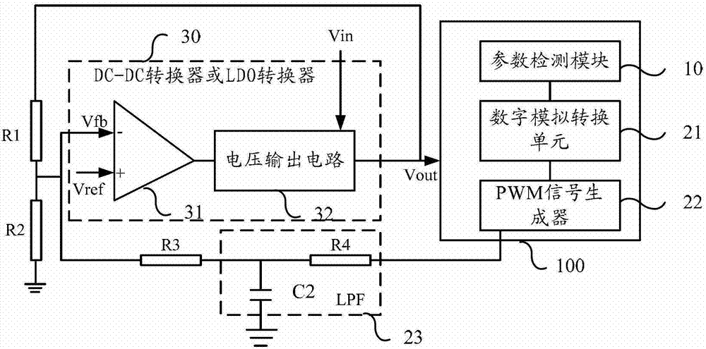
[0018] figure 1 It is a schematic structural diagram of a chip dynamic voltage regulation circuit provided by Embodiment 1 of the present invention. The circuit is suitable for supplying power to a system equipped with an SOC chip and has dynamic voltage regulation capability. The circuit specifically includes: a parameter detection module 10 , a PWM (Pulse-Width Modulation, Pulse-Width Modulation) signal generation module and a power supply module 30 . Among them, the parameter detection module 10 is used to detect the attribute parameters of the chip 100, which can be set in the chip 100, and can also be set independently of the chip 100, as long as the parameter detection function can be completed; The parameters generate corresponding PWM digital signals, and the PWM digital signals are converted into analog signals with DC voltage through a low-pass filter; the power supply module 30 includes a DC-DC converter or a low dropout linear regulator (Low DropOut regulator , re...
Embodiment 2
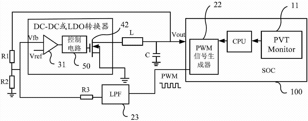
[0033] image 3 It is a schematic structural diagram of a chip dynamic voltage regulation circuit provided in Embodiment 2 of the present invention. The parameter detection module in this embodiment includes a chip process monitor (PVT Monitor) 11 for detecting process attribute parameters of the chip 100 . The chip process monitor 11 can use the existing technology to detect the chip process, mainly to detect the process value of the chip 100, for example, FF, TT or SS type chips have different process values, which are divided according to certain numerical ranges.
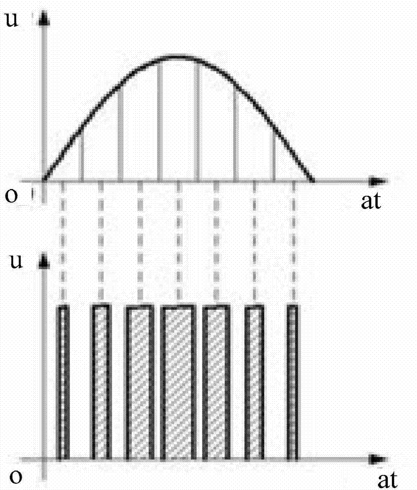
[0034] In the PWM signal generation module, the digital-to-analog conversion unit is used to convert the detected attribute parameters into corresponding voltages based on the set mapping relationship. This function can be realized in the form of software by the existing CPU in the chip. Those skilled in the art can know the structure of a conventional PWM signal generator, which will not be repeated here.
[0...
PUM
 Abstract
Description
Claims
Application Information