Drive protection circuit of insulated gate bipolar transistor (IGBT)
A technology for driving protection circuits and driving chips, which is applied in the direction of electrical components, electronic switches, pulse technology, etc., can solve problems such as poor stability, heavy workload, and complex structure, and achieve the effect of ensuring reliability and preventing misoperation
- Summary
- Abstract
- Description
- Claims
- Application Information
AI Technical Summary
Problems solved by technology
Method used
Image
Examples
Embodiment Construction
[0009] The detailed structure of the present invention is illustrated in conjunction with examples.
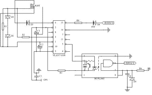
[0010] The IGBT drive protection circuit diagram is shown in figure 1 As shown, the driver chip is VLA517-01R, the isolation optocoupler is HCPL2602, and the voltage limiting diode is 1N4733 and 1N4744.
[0011] After VLA517-01R receives the driving signal, when 10mA current flows through the input pins 15 and 14, the internal optocoupler is turned on, and the driving voltage of +15V output from pin 3 makes the IGBT turn on, the driving signal is cut off, and the optocoupler is turned off. 3 The pin outputs a reverse -5V voltage to turn off the IGBT. 1N4733 and 1N4744 limit the voltage input to the IGBT to a maximum of 15V and a minimum of -5V to reliably drive the IGBT on and off. When the system fails, VLA517-01R blocks the signal output of pin 3, and at the same time, the output fault signal is sent to the processor after being isolated by the optocoupler HCPL2602. Becau...
PUM
 Abstract
Description
Claims
Application Information
 - R&D
- Intellectual Property
- Life Sciences
- Materials
- Tech Scout
- Unparalleled Data Quality
- Higher Quality Content
- 60% Fewer Hallucinations
Browse by: Latest US Patents, China's latest patents, Technical Efficacy Thesaurus, Application Domain, Technology Topic, Popular Technical Reports.
© 2025 PatSnap. All rights reserved.Legal|Privacy policy|Modern Slavery Act Transparency Statement|Sitemap|About US| Contact US: help@patsnap.com

