
Test instrument sharing usage method and test system in automatic optical module test

An automatic test system and optical module testing technology, applied in the field of optical modules, can solve the problems of waste of instrument use, idle state of test instruments, and low utilization rate of instruments, so as to avoid waste, save test time, and increase the utilization rate of instruments.

Inactive Publication Date: 2013-02-13
绍兴飞泰光电技术有限公司
View PDF3 Cites 21 Cited by
  • Summary
  • Abstract
  • Description
  • Claims
  • Application Information

AI Technical Summary

Problems solved by technology

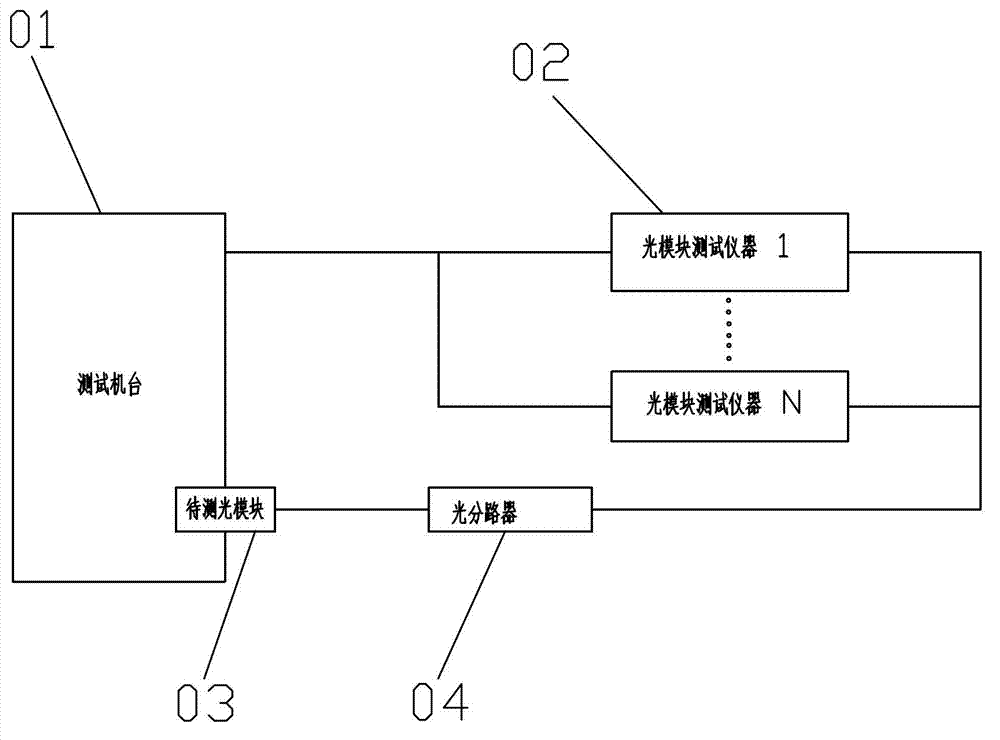
[0006] The above system has a simple structure and is easy to connect, but during the test process, the test time for a certain performance of a single optical module only takes up a small part of the entire test process, causing the rest of the test instruments to be idle for a long time
[0007] It can be seen that, although the above-mentioned existing testing system and method are convenient to use in terms of structure, method and use, the utilization rate of the instrument is not high, and there is a serious waste of instrument use. Obviously, there are still inconveniences and defects, and it is urgent to be further improved.

Method used


Image

  • Test instrument sharing usage method and test system in automatic optical module test
  • Test instrument sharing usage method and test system in automatic optical module test

Examples


Embodiment Construction

[0033] The present invention will be further described below in conjunction with the accompanying drawings and specific embodiments.

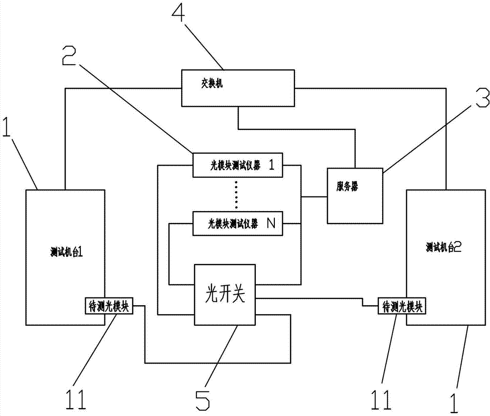
[0034] like figure 2 As shown, a kind of optical module automatic test system disclosed by the present invention includes two test machines 1, an optical module to be tested 11, an optical module tester 2, a server 3, a switch 4, and an optical switch 5; the test machine 1 passes The network cable is connected to the switch 4, the switch 4 is connected to the server 3 through the network cable, the server 3 is connected to all the optical module test instruments 2 through the GPIB line, the optical module test instrument 2 is connected to the optical switch 5 through the optical fiber jumper, and the optical switch 5 is connected to the optical switch 5 through the optical fiber The jumper is connected to the optical module 11 to be tested.

[0035] The working process of the present invention is:

[0036] First, the system is initialize...


PUM


Abstract

The invention discloses a test instrument sharing usage method and a test system in an automatic optical module test. The system comprises a plurality of testing machine platforms, optical modules to be tested, optical module testing instruments, servers, switchboards and optical switches, wherein the testing machine platforms are connected with the switchboards, the switchboards are connected with the servers, the servers are connected with all the optical module testing instruments, and the optical module testing instruments are with the optical modules to be tested which are arranged on the testing machine platforms through the optical switches. Control is achieved through servers, when a testing machine platform requires an optical module testing instrument, the testing machine platform applies for resources of the instrument for a server, when the instrument idles, the server distributes the resources of the instrument to the testing machine platform, at the same time, the instrument is remarked to be occupied until the testing machine platform releases the usage of the platform, and if one instrument is occupied by one of the testing machine platforms , the other testing machine platform can apply for the usage of other instruments. According to the method and the system, by the aid of the server, testing resources are coordinated, a plurality of optical modules can be detected, and the utilization rate of the instruments can be improved.

Description

[0001] technical field [0002] The invention relates to the field of optical modules, in particular to a method for sharing and using testing instruments in automatic testing of optical modules and a testing system. [0003] Background technique [0004] With the sharp increase in demand for high-quality communication services, the demand for optical modules in optical communication systems has also increased sharply. Therefore, optical module manufacturers need to increase production capacity to meet market demand. [0005] In the production process of optical modules, some expensive instruments are needed, such as figure 1 As shown, a schematic diagram of an existing optical module testing system: including a testing machine 01, an optical module testing instrument 02, an optical module to be tested 03 is arranged on the testing machine 01, and the testing machine 01 is respectively connected to the testing machine 01 through a GPIB connection line. A series of opti...

Claims


Application Information

Patent Timeline
IPC IPC(8): H04B10/073H04B10/25
Inventor 吴剑锋凌波
Owner 绍兴飞泰光电技术有限公司
Learn More