A system for controlled on demand in situ hydrogen generation using a recyclable liquid metal reagent, and method used in the system

一种发生系统、试剂的技术,应用在在高温下液体与气体的反应、氢/合成气生产、氢的生产等方向,能够解决毒性高、回收燃料昂贵、技术复杂等问题

Inactive Publication Date: 2013-02-13
阿马利奥·加里多埃斯库德罗
View PDF19 Cites 3 Cited by
  • Summary
  • Abstract
  • Description
  • Claims
  • Application Information

AI Technical Summary

Problems solved by technology

[0016] Most conventional hydrogen generation systems require catalysts and / or ignition systems which are expensive in terms of refueling or use highly toxic substances
Although most of these systems can be installed on motor vehicles, they are technically complex or involve technical, economical or environmental deficiencies in providing sufficient hydrogen flow generation accuracy and sensitivity for instantaneous response to power demand. performance (for example, as required for direct injection into internal combustion engines or turbines) and especially in terms of recycling spent fuel

Method used


Image

  • A system for controlled on demand in situ hydrogen generation using a recyclable liquid metal reagent, and method used in the system
  • A system for controlled on demand in situ hydrogen generation using a recyclable liquid metal reagent, and method used in the system
  • A system for controlled on demand in situ hydrogen generation using a recyclable liquid metal reagent, and method used in the system

Examples


Embodiment Construction

[0171] Embodiment of the invention

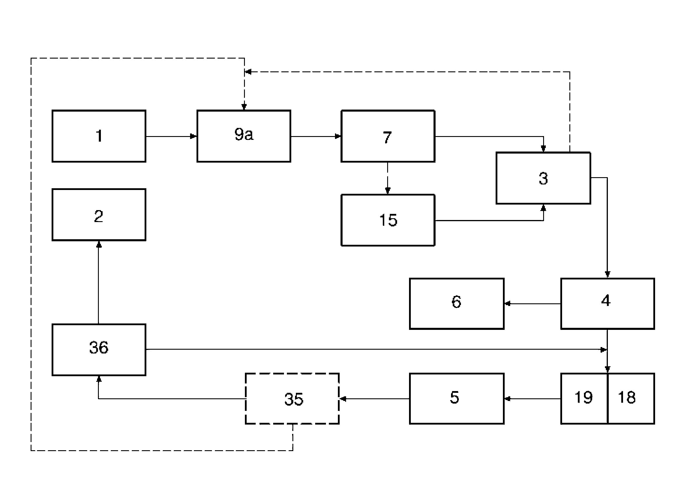
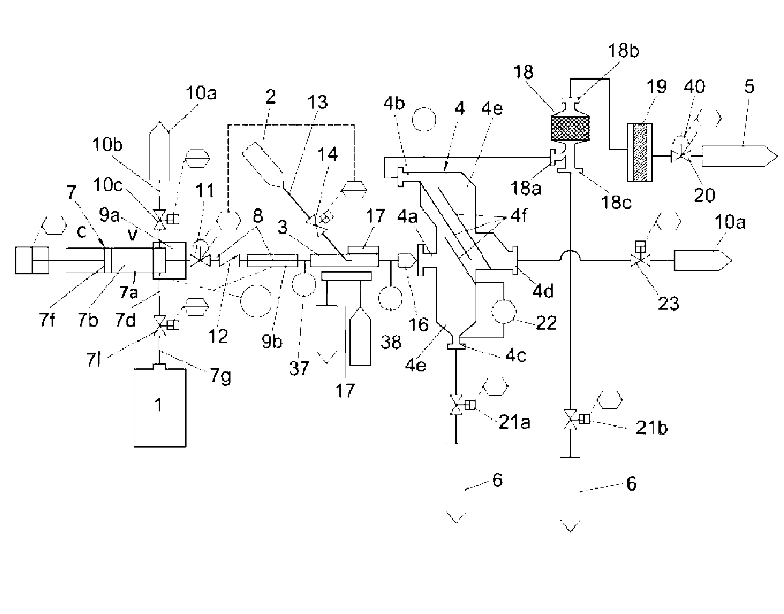
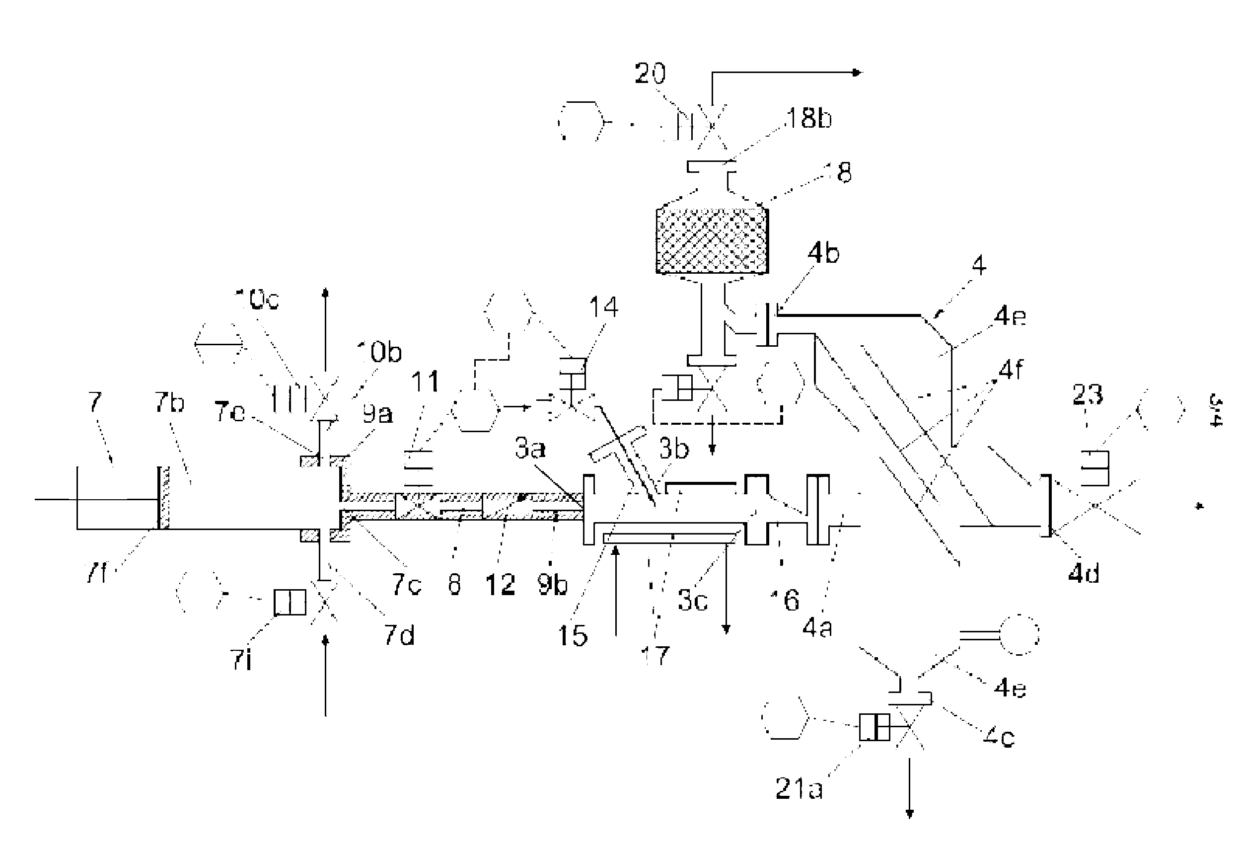
[0172] Figure 1 to Figure 3 Shown are the basic steps and elements of hydrogen generation according to one embodiment of the present invention.

[0173] The basic steps of the described embodiment are as figure 1 shown in , and will be described based on the use of an alkali metal such as lithium or sodium as the first reagent, but the steps can also be followed in a similar manner using alkaline earth metals or alloys of these metals.

[0174] The alkali metal contained in the first storage device 1 is heated to a temperature above its melting point by the first reagent heating device 9a, and the liquefied alkali metal is extruded (preferably using an extruder die of controlled size) using a metal reagent injection device 7 head) into the reactor 3. At the same time, liquid demineralized cold water from the second storage device 2 is also injected into the reactor 3 through the water injection device 15 . The water injection device 1...


PUM

PropertyMeasurementUnit
melting pointaaaaaaaaaa

Abstract

A hydrogen generating system and a method of in situ hydrogen generation controlled on demand capable of reacting an aluminum-free metal reagent selected from alkali metals, alkaline earth metals, alkali metal alloys and blends consisting of alkali metals, alkaline earth metal alloys and blends consisting of alkaline earth metals and metal alloys consisting of at least one alkali metal and at least one alkaline earth metal, with water to obtain hydrogen and a residual reaction product comprising metal hydroxide selected from alkali hydroxides and alkaline earth hydroxide; and separating hydrogen from the residual reaction product; liquefying the metal reagent by heating to obtain liquid metal reagent under vacuum conditions; injecting the liquid metal reagent into a reactor (3) by metal reagent injecting means (7,8) and simultaneously injecting, by water injection system (13, 14, 15), a stoichiometric amount of water with respect to the amount of the liquid metal reagent being injected into the reactor (3) such that a controlled metal reagent / water ratio is maintained in the reactor (3); transferring hydrogen and the residual reaction product from the reactor (3) to separation means (4, 18); separating hydrogen from the residual reaction product; transferring separated hydrogen to hydrogen receiving means (5) and transferring the residual reaction product to metal hydroxide receiving means (6), keeping the metal reagent injecting means (7,8) water injection system (13, 14, 15), the reactor (3), the separating means (4, 18) and the hydrogen receiving means (5) free of oxygen by selectively providing a vacuum in the system.

Description

technical field [0001] The invention belongs to the technical field of the chemical generation of hydrogen using alkali metals and alkaline earth metals and the recovery of alkali metals and alkaline earth metals from the corresponding hydroxides. [0002] The invention is particularly useful in controllable hydrogen generation in amounts corresponding to variable demands, such as vehicles equipped with internal combustion engines, turbines or hydrogen batteries, such as vehicles for land, air or water sports, and any vehicle used for Any other device that requires on-demand hydrogen generation. Background technique [0003] Hydrogen can be used as a polluting fuel in fuel cells, internal combustion engines or turbines, and any other system that uses gaseous hydrogen as fuel. Obviously, a power generation system using hydrogen as fuel requires hydrogen to be produced through a generation process. Generally, the hydrogen produced by this generation process is stored in a st...

Claims


Application Information

Patent Timeline
Patent Type & Authority Applications(China)
IPC IPC(8): C01B3/08C01B3/10B01J4/02C01B3/50
CPCH01M2250/20Y02T90/32C01B3/08H01M4/00C01B2203/169Y02E60/50B01J2219/00186B01J4/02C01B2203/0465B01J4/008B01J10/005C01B3/50C01B3/10Y02E60/36H01M8/04208Y02T90/40
Inventor 阿马利奥·加里多埃斯库德罗
Owner 阿马利奥·加里多埃斯库德罗
Why Eureka
Try Eureka