Metal section mould with controllable cross section and gravity slantingly-rotated foundry technique of aluminum alloy cylinder cover of metal section mould

A metal type and controllable technology, applied in metal processing equipment, manufacturing tools, casting molding equipment, etc., can solve problems such as shrinkage cavity, affecting gas discharge, shrinkage porosity, etc., achieve stable mold filling and increase yield

Inactive Publication Date: 2013-02-20
WENZHOU RUIMING IND
View PDF5 Cites 21 Cited by
  • Summary
  • Abstract
  • Description
  • Claims
  • Application Information

AI Technical Summary

Problems solved by technology

However, metal type gravity casting has defects such as long mold production cycle, high cost, low cylinder head yield, and easy shrinkage and porosity. Easy to produce defects such as pores, shrinkage cavities and shrinkage porosity
[0003] The metal mold used in the above-mentioned metal mold gravity tilting casting aluminum cylinder head process includes sprue cup, riser sand core, molding module, ejector device, water cooling device, negative pressure suction device, etc. The sprue cup In the process of gravity tilting pouring, while the liquid aluminum will enter the casting cavity from the side riser of the intake side cover, part

Method used


Image

  • Metal section mould with controllable cross section and gravity slantingly-rotated foundry technique of aluminum alloy cylinder cover of metal section mould
  • Metal section mould with controllable cross section and gravity slantingly-rotated foundry technique of aluminum alloy cylinder cover of metal section mould
  • Metal section mould with controllable cross section and gravity slantingly-rotated foundry technique of aluminum alloy cylinder cover of metal section mould

Examples


Embodiment Construction

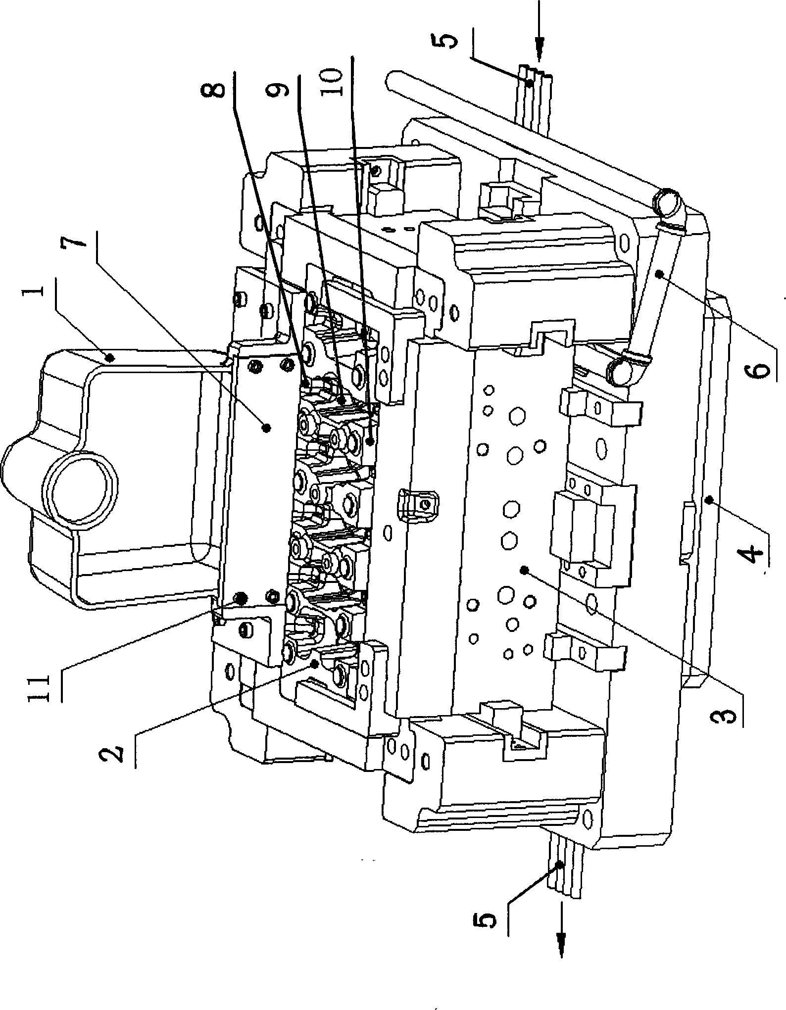
[0012] refer to figure 1 As shown, the present invention is applied to the cross-section controllable metal mold of the metal mold gravity tilting casting aluminum cylinder head process, including the sprue cup 1, the riser sand core 2, the molding module 3, the ejector device 4, and the water cooling device 5 , Negative pressure air extraction device 6, on the bottom of described sprue cup 1, and at the intersection of sprue cup 1 and riser sand core 2 (by screw 11) control section baffle plate 7 is housed. The sprue cup can also be called a controlled section sprue cup. The gravity tilting (control section) casting process of the aluminum alloy cylinder head obtained according to the cross-section controllable metal mold is: the first step is core making: the aluminum alloy cylinder head is water-jacketed with sand core, intake and exhaust passages The sand core, the oil chamber sand core and the riser sand core are manufactured and assembled respectively; the second step i...


PUM


Abstract

The invention discloses a metal section mould with a controllable cross section and a gravity slantly-rotated foundry technique of an aluminum alloy cylinder cover of the metal section mould. The metal section mould comprises a pouring cup (1), a dead head sand core (2), a molding module (3), an ejector device (4), a water cooling device (5) and a negative pressure air extractor (6), and a control cross section retaining plate (7) is installed at the intersection position of the pouring cup and the dead head sand core on the lower portion of the pouring cup (1). Molten aluminum can only enter a casting cavity from a dead head beside an air inlet lateral cover due to retaining functions of the control cross section retaining plate in a slantingly-rotated pouring process, then the molten aluminum is discharged from a dead head at the position of a middle spark plug and a dead head beside an air discharge lateral cover, stable molten aluminum mold filling in a mold filling process is achieved, a principle of mold filling sequence and air inlet and air outlet in sequence is followed, the whole mold filling speed and time of a casting piece are controlled by controlling the minimum mold filling cross section of the pouring cup, defects such as air holes, shrinkage holes and shrinkage porosities produced by an original piece are obviously overcome, and accordingly product yield, acceptability and quality of the metal casting piece are improved.

Description

technical field [0001] The invention relates to a metal mold for aluminum alloy casting technology and the aluminum alloy cylinder head casting technology thereof. Background technique [0002] The structure of the cylinder head of an automobile engine is complex, consisting of multi-layer cavities, and no leakage is allowed in each cavity, and its wall thickness is uneven, making casting difficult. At present, the casting process methods for producing engine aluminum cylinder heads at home and abroad include metal mold gravity casting process, low pressure casting process, special low pressure casting process, lost foam casting process, sand mold low pressure casting process, metal type gravity tilting casting process, etc. : Metal mold gravity casting process and low pressure casting process are traditional, mature, and most used methods of casting aluminum alloys, and metal mold gravity tilting casting process is a gradually mature and widely used new technology. However...

Claims


Application Information

Patent Timeline
IPC IPC(8): B22C9/06B22C9/22B22C9/08
Inventor 叶锦瑞赵葵
Owner WENZHOU RUIMING IND
Why Eureka
Try Eureka