Capping device for filling container

A technology of container and power device, which is applied to flange-type bottle caps and other directions to achieve the effect of stable working performance and simple structure

Active Publication Date: 2013-02-20
HANGZHOU ZHONGYA MACHINERY CO LTD
View PDF7 Cites 13 Cited by
  • Summary
  • Abstract
  • Description
  • Claims
  • Application Information

AI Technical Summary

Problems solved by technology

The container capping mechanism of this type of structure in the prior art is only suitable for the cont

Method used


Image

  • Capping device for filling container
  • Capping device for filling container
  • Capping device for filling container

Examples


Embodiment Construction

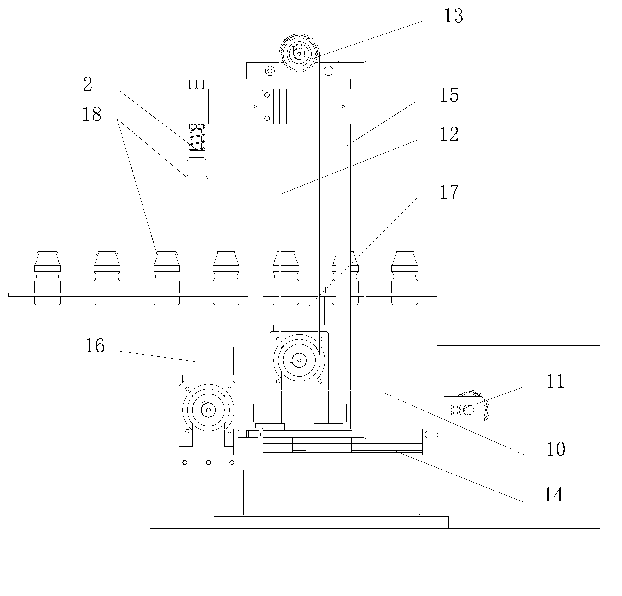
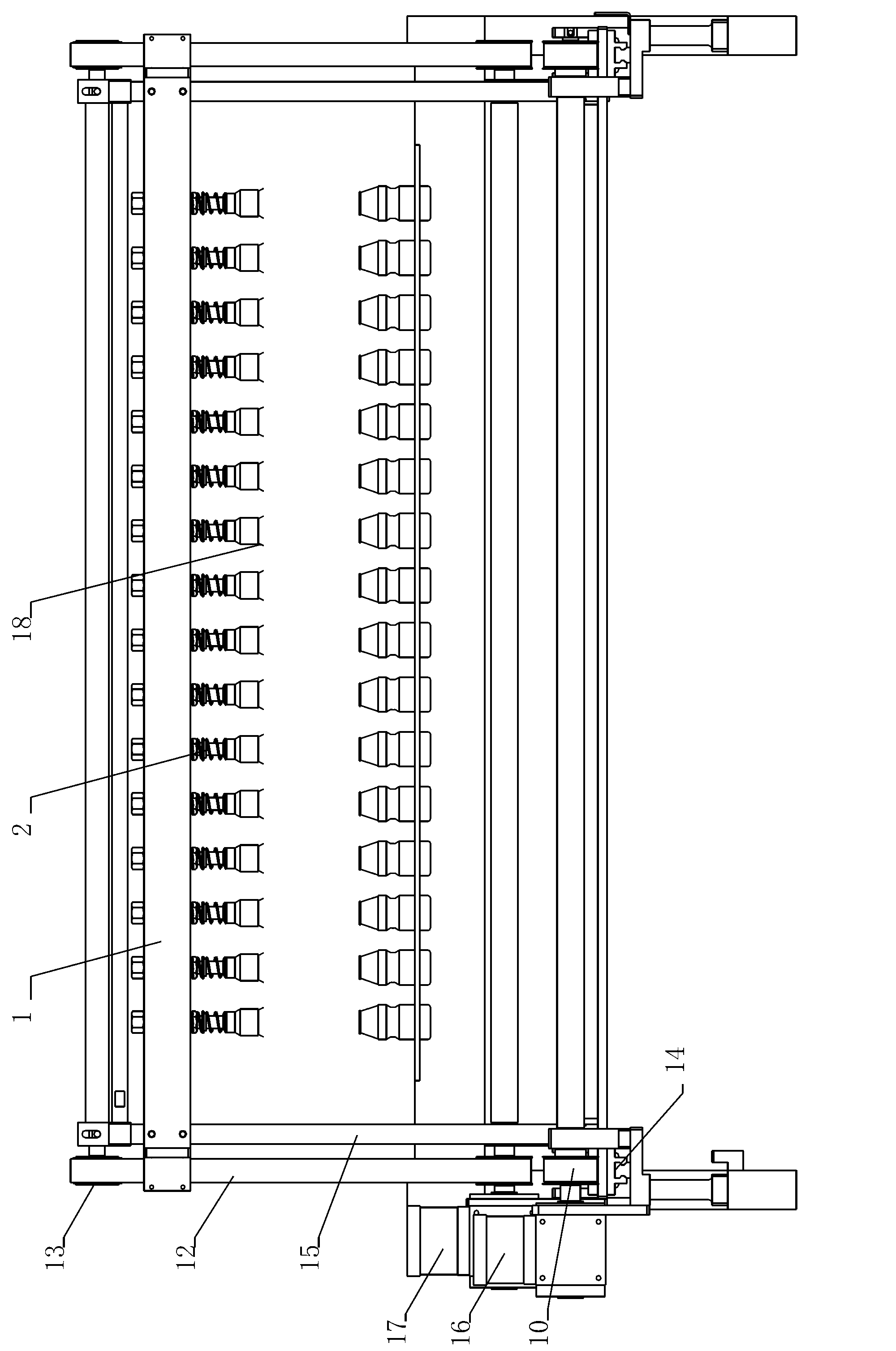
[0031] The first embodiment of the present invention, such as figure 1 , 2 As shown, the capping device for container filling includes a horizontal servo mechanism, a vertical servo mechanism and a capping mechanism. The horizontal servo mechanism and the vertical servo mechanism jointly constitute the station adjustment mechanism. The horizontal servo mechanism, the vertical servo mechanism and the capping mechanism are all installed on the frame of the capping device for container filling.

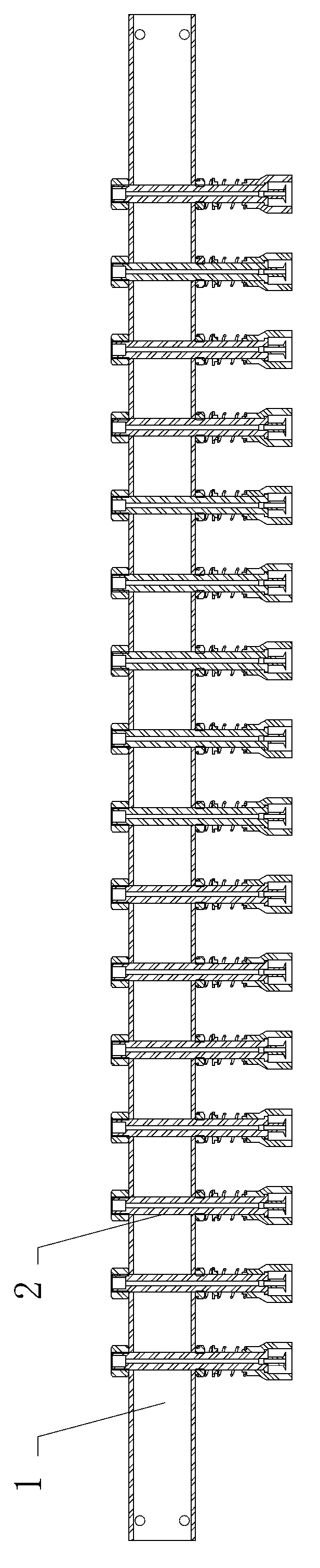
[0032] Such as image 3 , 4, Shown in 5, the capping mechanism includes a bracket 1, a capping head 2 for the suction pressure cap. The support 1 is a straight strip structure, and the suction and pressure capping heads 2 are vertically distributed on the support 1 at equal intervals, and the suction and pressure capping heads 2 and the support 1 are fixedly connected. The suction and pressure capping head 2 includes a vacuum suction pipe 3 and a capping head 4 . The vacuum suction...


PUM


Abstract

The invention discloses a capping device for filling a container. The capping device for filling the container comprises a capping mechanism, a horizontal servo mechanism and a perpendicular servo mechanism, wherein the perpendicular servo mechanism is arranged on the horizontal servo mechanism and can do shift movement in a horizontal direction along with the horizontal servo mechanism, and the capping mechanism is arranged on the perpendicular servo mechanism and can do shift movement in a vertical direction along with the perpendicular servo mechanism; and the capping device for filling the container simultaneously adsorbs multiple covers through a negative pressure adsorbing technology so as to realize capping operation for containers of the same quantity, thereby meeting the operating requirements of capping multiple containers, and meanwhile, being suitable for a step-by-step in-row bottle feeding filling process. The capping device for filling the container provided by the invention has the advantages that the structure is simple, the working performance is stable, and the capping device is safe and efficient.

Description

technical field [0001] The invention relates to a device for capping containers used in a filling production line. Background technique [0002] In the filling process of beverages, dairy products, cosmetics, lubricating oil, etc., the filled containers need to be capped and sealed. For example, Chinese Patent Publication No. 101885457A discloses a "capper hanging device for capping machines", which is specially used for capping containers, so that the subsequent process is convenient for capping. The technical solution adopted in this patent is that the capping device of the capping machine includes a capping device and a capping device, the capping device is connected to a conveyor belt, baffles are arranged on both sides of the conveyor belt, and a capping device is arranged upstream of the conveyor belt. The outlet of the lid hanging device is located above the conveyor belt, and the height of the outlet from the conveyor belt is slightly greater than the height of the ...

Claims


Application Information

Patent Timeline
IPC IPC(8): B67B3/02B67B3/06
Inventor 史正姜钰刘香
Owner HANGZHOU ZHONGYA MACHINERY CO LTD
Why Eureka
Try Eureka