
Dual-frequency impedance-matching network

An impedance matching network and impedance matching technology, applied in impedance matching network, multi-terminal pair network, etc., can solve the problems of large volume, long total length, large size, etc., achieve compact circuit design, save circuit layout space, design reasonable effect

Inactive Publication Date: 2013-02-20
NANJING UNIV OF INFORMATION SCI & TECH
View PDF5 Cites 5 Cited by
  • Summary
  • Abstract
  • Description
  • Claims
  • Application Information

AI Technical Summary

Problems solved by technology

[0013] However, in the existing dual-frequency impedance matching network, some schemes have a large size, and some schemes have a long total length, and basically all of them have the defect of large volume.

Method used


Image

  • Dual-frequency impedance-matching network
  • Dual-frequency impedance-matching network
  • Dual-frequency impedance-matching network

Examples


Embodiment Construction

[0055] The technical solutions provided by the present invention will be described in detail below in conjunction with specific examples. It should be understood that the following specific embodiments are only used to illustrate the present invention and are not intended to limit the scope of the present invention.

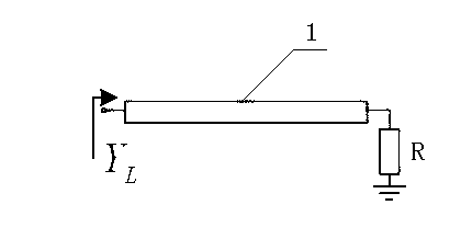
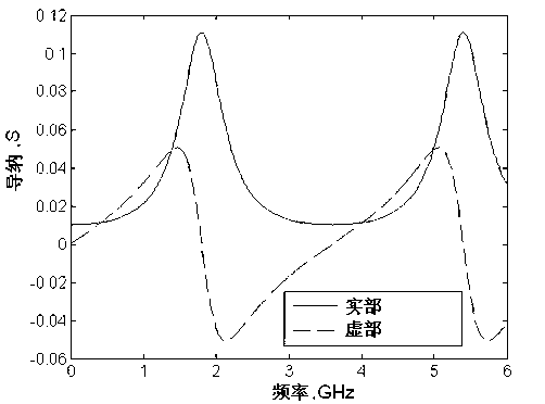
[0056] figure 1A complex load that varies with frequency is constructed in . The complex load includes a section of transmission line with characteristic impedance Zc=30Ω, electrical length θ=50deg1GHz, that is, a transmission line with an electrical length of 50 degrees at a frequency of 1GHz, and a 100-ohm resistor at the end of the transmission line. The real and imaginary parts of the input admittance of this load are plotted at figure 2 middle.

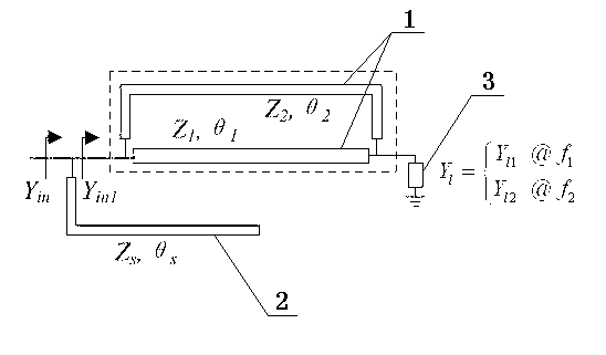
[0057] According to the above complex load design such as image 3 The shown dual-frequency impedance matching network is composed of a parallel transmission line structure and a stub line 2 cascaded, wherein th...


PUM


Abstract

The invention discloses a microwave dual-frequency impedance-matching network which consists of parallel transmission lines and a stub line. According to the dual-frequency impedance-matching network, the real impedance matching can be realized nearby two frequency points aiming at specific frequency-related complex impedance. The dual-frequency impedance-matching network disclosed by the invention is arranged between a radio frequency source and a load and consists of a parallel transmission line structure and a stub line in cascade, wherein the parallel transmission line structure comprises two transmission lines which are parallel to each other, and the dual-frequency impedance matching between the radio frequency source and the load is realized by the network. According to the dual-frequency impedance-matching network, the three transmission lines can be arranged side by side, so that the circuit is compact, the line arrangement space is greatly reduced, and the overall length of the circuit is shorter. The dual-frequency impedance-matching network is reasonable in design, has higher design freedom and adaptability, can adapt to various different load conditions and is wide in application range, and the frequency ratio of two applicative frequency points is high.

Description

[0001] technical field [0002] The invention belongs to the technical field of wireless communication, and in particular relates to a dual-frequency impedance matching network capable of supporting multiple frequency bands. Background technique [0003] In the process of signal or electric energy transmission, in order to achieve signal transmission without reflection or maximum power transmission, it is required that the circuit connection achieve impedance matching. Impedance matching is related to the performance of the system, and the impedance matching of the circuit can make the performance of the system reach the optimum under the agreed criteria. [0004] The concept of impedance matching is not only applicable to the field of strong current, but also to the field of weak current; not only to analog circuit, but also to digital circuit; not only to low frequency and low speed circuit, but also to high frequency, high speed and microwave circuit. Impedance match...

Claims


Application Information

Patent Timeline
IPC IPC(8): H03H11/28
Inventor 崔萌萌刘云
Owner NANJING UNIV OF INFORMATION SCI & TECH
Learn More