Defoaming device and defoaming method for removing foam of drilling fluid by means of linkage of negative pressure and thermal radiation
A defoaming device and heat radiation technology, which is applied in the direction of earthwork drilling, flushing wellbore, wellbore/well parts, etc., can solve the problem of single defoaming method and achieve the effect of saving energy
- Summary
- Abstract
- Description
- Claims
- Application Information
AI Technical Summary
Problems solved by technology
Method used
Image
Examples
Embodiment 1
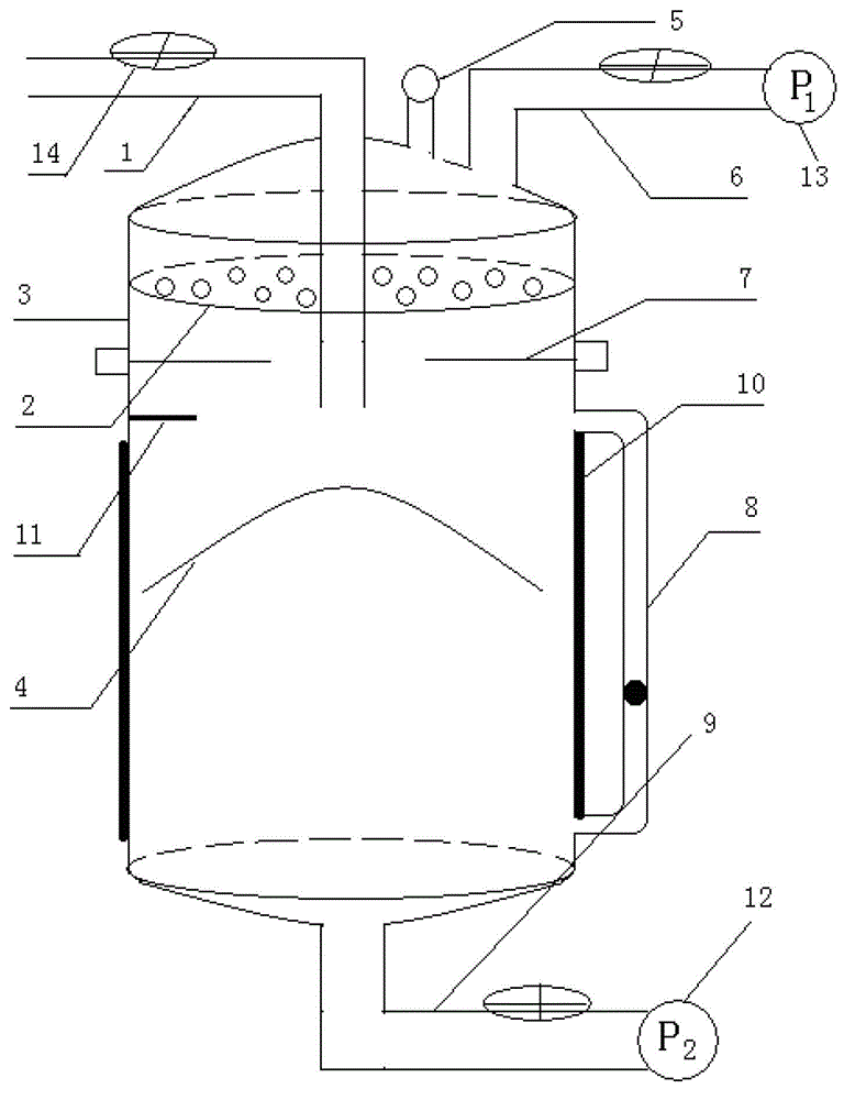
[0040] Embodiment 1 of the present invention such as figure 1 As shown, it includes a cylindrical tank body 3, which is characterized in that the top of the tank body 3 has a foam inlet 1, a gas outlet 6 and a manometer 5 with a pressure sensor, the foam inlet 1 is connected to a control valve 14; the gas outlet 6 Connect the vacuum pump 13; the upper part of the tank body 3 is provided with a perforated partition 2, the heat radiation part 7 is provided under the perforated partition 2, the middle position of the tank body 3 is located below the heat radiation part 7, and the umbrella plate 4 is arranged, and the heat radiation part 7 A temperature sensor 11 is set in the middle of the umbrella plate 4; a liquid level sensor 8 is installed in the middle and lower part of the side of the tank body, and a layer of heating tape 10 is covered on the periphery of the tank body 3; The slag outlet 9 is connected to the water pump 12; the pressure sensor on the pressure gauge 5, the ...
Embodiment 2
[0045] A method for defoaming using the above-mentioned negative pressure and heat radiation linkage defoaming device, the steps are as follows:
[0046] 1) Connect the DC power supply and power supply in the defoaming device, and the pressure sensor, temperature sensor and liquid level sensor on the pressure gauge start to work;
[0047] 2) Set the temperature range of the temperature sensor to 50-100°C, turn on the power control switch of the heat radiation part and the heating cable to start heating, when the temperature in the tank is higher than the upper limit of the set value by 100°C, turn off the heat The power control switch of the radiating part and the heating cable makes it stop heating, and then the heating cable turns to the heat preservation mode. When the temperature in the tank is lower than the lower limit of the set value by 50°C, the power control switch of the heat radiation part and the heating cable is turned on to make it start heating;
[0048] 3) Un...
Embodiment 3
[0053] Same as Example 2, except that the internal pressure of the tank is different from the speed at which the foam is introduced.
[0054] 1) Connect the DC power supply and power supply in the defoaming device, and the pressure sensor, temperature sensor and liquid level sensor on the pressure gauge start to work;
[0055] 2) Set the temperature range of the temperature sensor to 50-100°C, turn on the power control switch of the heat radiation part and the heating cable to start heating, when the temperature in the tank is higher than the upper limit of the set value by 100°C, turn off the heat The power control switch of the radiating part and the heating cable makes it stop heating, and then the heating cable turns to the heat preservation mode. When the temperature in the tank is lower than the lower limit of the set value by 50°C, the power control switch of the heat radiation part and the heating cable is turned on to make it start heating;
[0056] 3) Under the abov...
PUM
 Abstract
Description
Claims
Application Information
 - R&D
- Intellectual Property
- Life Sciences
- Materials
- Tech Scout
- Unparalleled Data Quality
- Higher Quality Content
- 60% Fewer Hallucinations
Browse by: Latest US Patents, China's latest patents, Technical Efficacy Thesaurus, Application Domain, Technology Topic, Popular Technical Reports.
© 2025 PatSnap. All rights reserved.Legal|Privacy policy|Modern Slavery Act Transparency Statement|Sitemap|About US| Contact US: help@patsnap.com

