Adjustable-pressure and adjustable-flow buffer hydraulic cylinder, control method and hydraulic system

A technology for buffering hydraulic cylinders and flow rates, which is applied in the fields of control methods and hydraulic systems, buffering hydraulic cylinders, hydraulic cylinders, control methods and hydraulic systems, and can solve problems such as difficulty in achieving synchronization, complex buffering devices, and complex implementation processes.

Active Publication Date: 2013-02-27
CRCC HIGH TECH EQUIP CORP LTD
View PDF9 Cites 14 Cited by
  • Summary
  • Abstract
  • Description
  • Claims
  • Application Information

AI Technical Summary

Problems solved by technology

[0003] Existing hydraulic cylinders are generally composed of a cylinder head, a cylinder barrel, and a piston. The pressure and flow of the hydraulic cylinder can only be adjusted as a whole by adjusting the oil supply pressure and flow of the system, and the pressure and flow of one chamber of the hydraulic cylinder cannot be adjusted separately. , and the buffer device is more complicated, the buffer effect is not ideal
[0004] For example, the Chinese utility model patent No. 201120365015.X discloses a buffer hydraulic cylinder, which includes a cylinder body, an end cover, a piston, a sealing ring, an oil inlet hole, and a current-limiting metal ring, and the piston rod The near piston end is provided with a guide groove that is farther away from the piston, and the angle of its deviation from the piston rod axis is greater. The part of the piston rod with the guide groove is thicker and cannot extend out of the end cover. The current limiting metal ring is set on the inner wall of the cylinder and can Rotate, the current-limiting metal ring has a contact rod extending into the guide groove, the farthest distance between the current-limiting metal ring and the end cover is equal to the length of the thicker part of the piston rod, there is a small hole on the current-limiting metal ring, and the oil inlet is set On the contact wall between the current-limiting metal ring and the cylinder body, the angle between the center of the oil inlet and the small hole and the axis of the piston is equal to the angle of the guide groove offset in the piston circumferential direction, and the relative displacement between the oil inlet and the small hole Always connected during the process, the buffer hydraulic cylinder can reduce the impact of the piston on the bottom of the cylinder and achieve buffering, but the realization process is more complicated
[0005] For example, the Chinese invention patent with the patent number of 200710306527.7 relates to a composite hydraulic cylinder and method with cushioning capacity, which can absorb the impact force generated when the external tensile load suddenly disappears, and protect the hydraulic cylinder. The hydraulic cylinder includes the main plunger cylinder And the operating cylinder, the main cylinder head of the main plunger cylinder is sealed and connected with the main cylinder body, the main plunger is in the main cylinder body, the main plunger is a hollow body, and the operating cylinder body is sleeved on the main column In the hollow cavity of the plug, the piston rod extends to the C chamber of the master cylinder in the operating cylinder, and the piston rod is sealed by a sealing sleeve in the operating cylinder. The structure and control method of the hydraulic cylinder are simple, but many It is difficult to achieve synchronization only with hydraulic cylinders

Method used


Image

  • Adjustable-pressure and adjustable-flow buffer hydraulic cylinder, control method and hydraulic system
  • Adjustable-pressure and adjustable-flow buffer hydraulic cylinder, control method and hydraulic system
  • Adjustable-pressure and adjustable-flow buffer hydraulic cylinder, control method and hydraulic system

Examples


Embodiment Construction

[0045] The present invention will be described in detail below in conjunction with the accompanying drawings and specific embodiments. The following description is only for demonstration and explanation, and does not limit the present invention in any form.

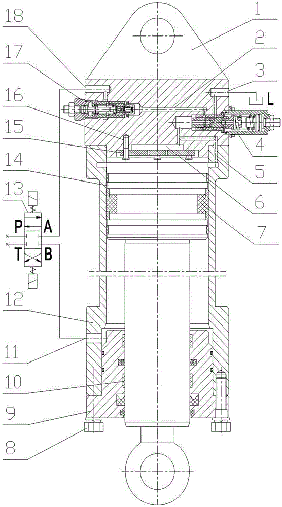
[0046] Such as figure 1 As shown, a buffer hydraulic cylinder with adjustable pressure and flow includes a cylinder barrel 12, an upper cylinder head 1, a lower cylinder head 9, and a piston 14. The cylinder barrel 12 is connected to the bottom of the upper cylinder barrel 1, and a piston is installed inside the cylinder barrel 12. 14. The piston 14 is covered with a piston seal 7, and the lower cylinder head 9 is fixed below the cylinder barrel 12 through bolts 8. The lower cylinder head 9 and the piston rod are sealed by the lower cylinder head seal 10. The lower part of the cylinder barrel 12 is provided with a lower Control oil port 11, upper control oil port 18 on the left side of upper cylinder head 1, L oil drain p...


PUM


Abstract

The invention relates to an adjustable-pressure and adjustable-flow buffer hydraulic cylinder, a control method and a hydraulic system. The buffer hydraulic cylinder comprises a cylinder barrel, an upper cylinder cover, a lower cylinder cover and a piston. A cylinder barrel is connected below the upper cylinder cover. The piston is installed in the cylinder barrel. A piston seal is sheathed on the piston. A lower control oil port is arranged at the lower part of the cylinder barrel. An upper control oil port is arranged on the left side of the upper cylinder cover. A flow adjusting assembly and a pressure adjusting assembly are additionally arranged in the upper cylinder cover. The upper control oil port and the lower control oil port are connected with the hydraulic system through a reversing valve. The hydraulic cylinder control method and the hydraulic system disclosed by the invention have the advantages that the lowering speed and the pressure of a single hydraulic cylinder are adjusted by controlling the lifting and the lowering of a railway track bed sewage blowing and sucking device, four hydraulic cylinders synchronously move to lower down the sewage blowing and sucking device, the blowing and sucking device is guaranteed to move close to the surfaces of rails, supporting wheels are not crushed and impact is not produced during rapid lifting.

Description

technical field [0001] The invention relates to a buffer hydraulic cylinder with adjustable pressure and flow, a control method and a hydraulic system, in particular to a hydraulic cylinder, a control method and a hydraulic system for lifting and lowering control of a railway track bed blowing and sucking sewage device, belonging to railway Technical field of maintenance and maintenance facilities. Background technique [0002] Dirt, such as dust, solid debris, tiny stones, coal, and rail grinding debris, are often deposited on the surface of the railway track. When the train passes by, the dirt will be rolled up, affecting driving safety. Before the purging operation of the railway track bed, it is necessary to control the synchronous movement of the four hydraulic cylinders to put down the suction device; during operation, it is necessary to provide pressure to the upper chamber of the four hydraulic cylinders, and it can be adjusted to ensure that the suction device is al...

Claims


Application Information

Patent Timeline
Patent Type & Authority Applications(China)
IPC IPC(8): F15B15/22F15B15/20F15B13/04
Inventor 郭关柱
Owner CRCC HIGH TECH EQUIP CORP LTD
Why Eureka
Try Eureka