
Belt continuously variable transmission

A technology of continuously variable transmission and speed ratio, which is applied to components with teeth, belts/chains/gears, mechanical equipment, etc., and can solve the problem of high machining accuracy of hydraulic actuators, uncontrollable speed ratio adjustment accuracy, and hydraulic actuators. To solve the problems of low mechanism efficiency and achieve the effect of continuous stepless change, convenient control and high precision of speed ratio adjustment

Active Publication Date: 2013-02-27
江苏久通汽车零部件有限公司
View PDF5 Cites 7 Cited by
  • Summary
  • Abstract
  • Description
  • Claims
  • Application Information

AI Technical Summary

Problems solved by technology

However, the efficiency of the hydraulic actuator is low. Research shows that the hydraulic system accounts for about 60% of the power loss of the metal belt continuously variable transmission, while the metal belt friction transmission only accounts for about 30%. At the same time, the hydraulic actuator requires high machining accuracy. This leads to higher cost; while using the torque cam mechanical adjustment method, the change of the speed ratio of the continuously variable transmission is generally accompanied by the change of the engine working condition, that is, the engine cannot be maintained in the optimal working area and only the speed of the continuously variable transmission needs to be adjusted. Ratio to meet the requirements of load changes, speed ratio adjustment accuracy can not be controlled

Method used


Image

  • Belt continuously variable transmission

Examples


Embodiment Construction

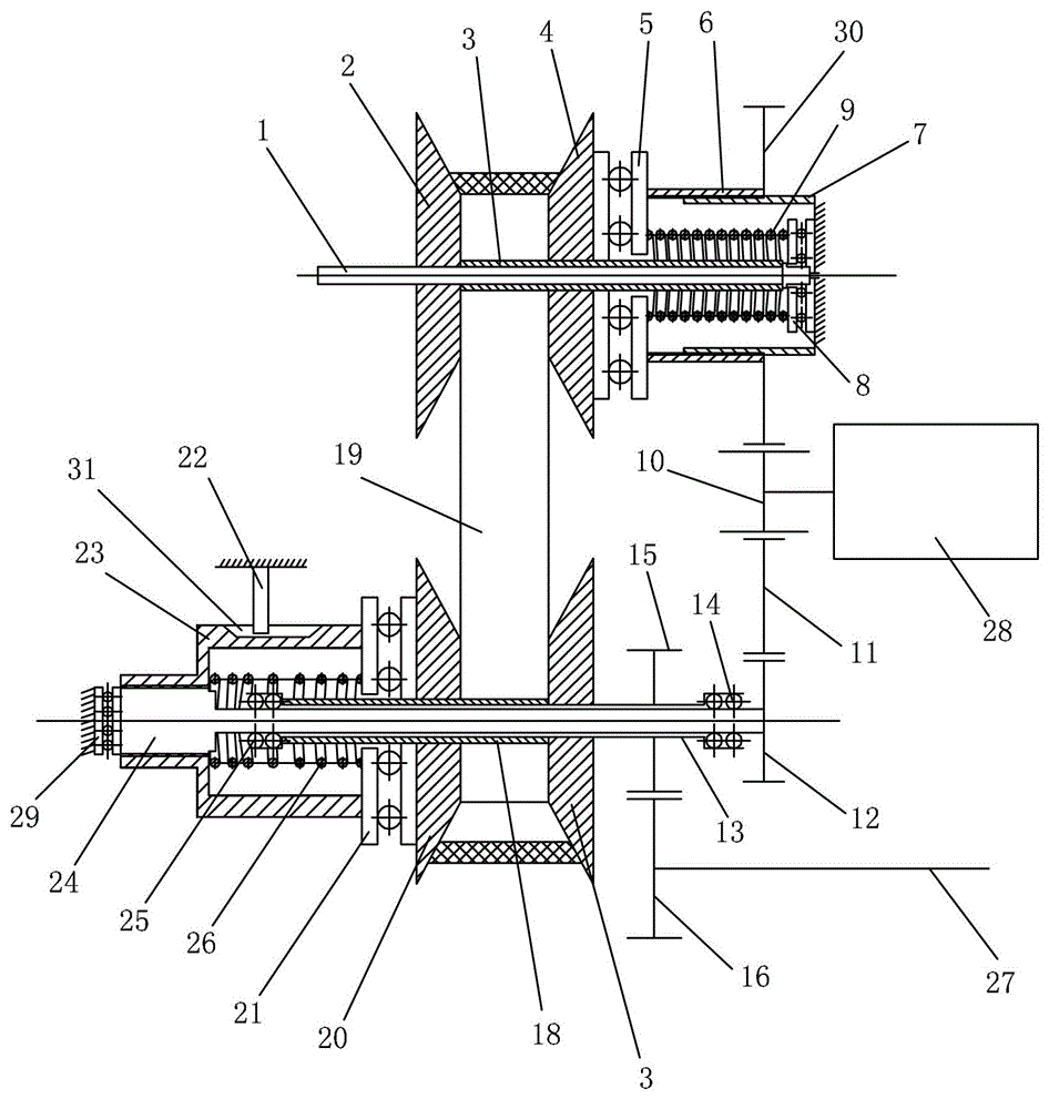
[0012] See figure 1 The speed ratio control device of the belt type continuously variable transmission of the present embodiment includes: a DC motor, a controller for controlling the steering and rotation angle of the output shaft of the DC motor, and a power input shaft 1 connected to the output shaft of the engine when in use. , the driving pulley that is located on the power input shaft 1, the power output shaft 13 that is connected with the vehicle transmission shaft 27 during use, the driven pulley that is located on the power output shaft 13, connects the driving pulley and The V-shaped transmission belt 19 of the driven pulley.

[0013] The driving pulley includes: a driving pulley fixed plate 2 fixed on the power input shaft 1, a driving sleeve 3 arranged on the right side of the driving pulley fixed plate 2 and vacantly sleeved on the power input shaft 1 , the driving pulley moving disc 4 that is empty on the driving shaft sleeve 3, the first device that is used t...


PUM


Abstract

The invention discloses a speed ratio control device of a continuously variable transmission. The speed ratio control device comprises a direct-current motor, a controller of the direct-current motor, two groups of gear transmission mechanisms, two groups of spiral lead screw mechanisms, two groups of spring force-assisting mechanisms, a plurality of plane bearings and a plurality of needle bearings. The direct-current motor serves as a power source of the transmission for speed ratio control, motor turning angle is converted to axial displacement of a belt pulley moving disc of the belt continuously variable transmission by controlling motor turning directions and turning angles through the two groups of gear transmission mechanisms and the spiral lead screw mechanisms correspondingly connected with the gear transmission mechanisms under matching of springs, and further continuous change of speed ratio of the continuously variable transmission in different working conditions is achieved by changing the contact radiuses of a V-shaped transmission belt and a driving belt wheel disc and a driven belt wheel disc.

Description

[0001] This application is a divisional application, the application number of the original application: 201010538238.1, the application date: November 10, 2010, and the name of the invention: the speed ratio control device of the belt type continuously variable transmission. technical field [0002] The invention belongs to a speed ratio control device of a belt-type continuously variable transmission, which is mainly used for automobiles and motorcycles using the continuously variable transmission, and can also be applied to other occasions that need to transmit power in a belt-type continuously variable transmission. Background technique [0003] The automobile transmission must adapt to the different requirements of the vehicle on the driving wheel traction and vehicle speed under different driving conditions such as starting, accelerating, driving and overcoming various road obstacles. In order to make full use of the power of the engine, improve the fuel economy and im...

Claims


Application Information

Patent Timeline
Patent Type & Authority Applications(China)
IPC IPC(8): F16H59/06F16H9/18F16H61/662F16H37/02
Inventor 张兰春贝绍轶赵景波
Owner 江苏久通汽车零部件有限公司
Learn More