Optical path assembly auxiliary device of three-axis integral optical fiber gyroscope

A fiber optic gyroscope and assembly-assisted technology, which is applied to measurement devices, Sagnac effect gyroscopes, instruments, etc., can solve the problems of increased difficulty, large volume and weight, complicated fiber routing paths and fiber coiling processes, etc. Simple and compact structure

Active Publication Date: 2013-02-27
BEIJING AEROSPACE TIMES OPTICAL ELECTRONICS TECH
View PDF3 Cites 5 Cited by
  • Summary
  • Abstract
  • Description
  • Claims
  • Application Information

AI Technical Summary

Problems solved by technology

The gyro inertial group composed of three single-axis fiber optic gyroscopes in a pairwise orthogonal manner is usually large in size and weight, and is not suitable for weapons with small diameters such as air-to-air missiles and torpedoes.
Taking the installation of fiber optic coils as an example, the three fiber optic coils are installed on three orthogonal planes of the gyro body; usually, when the optical path installation surface is located in the horizontal plane, it is convenient for the operator to install the fiber optic coils, which requires the installation of the optical path After the optical fiber coil is installed on the optical path installation surface, it is necessary to adjust the pose of the gyroscope body so that the next optical path installation surface to be installed with the optical fiber coil is located in the horizontal plane; in addition, since the optical devices are distributed in different On the installation surface of the optical path, the path of the optical fiber and the process of spinning the fiber become more complicated; due to the fragility of the optical fiber, the risk of tearing the optical fiber and damaging the optical device is easy to occur during the assembly process. Compared with the single-axis fiber optic gyro, the difficulty is greatly increased

Method used


Image

  • Optical path assembly auxiliary device of three-axis integral optical fiber gyroscope
  • Optical path assembly auxiliary device of three-axis integral optical fiber gyroscope
  • Optical path assembly auxiliary device of three-axis integral optical fiber gyroscope

Examples


Embodiment Construction

[0043] The present invention will be further described in detail below in conjunction with the accompanying drawings.

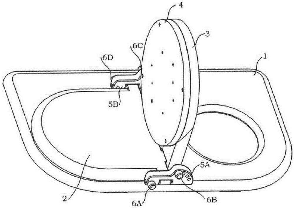
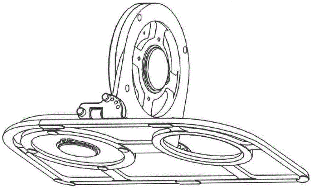
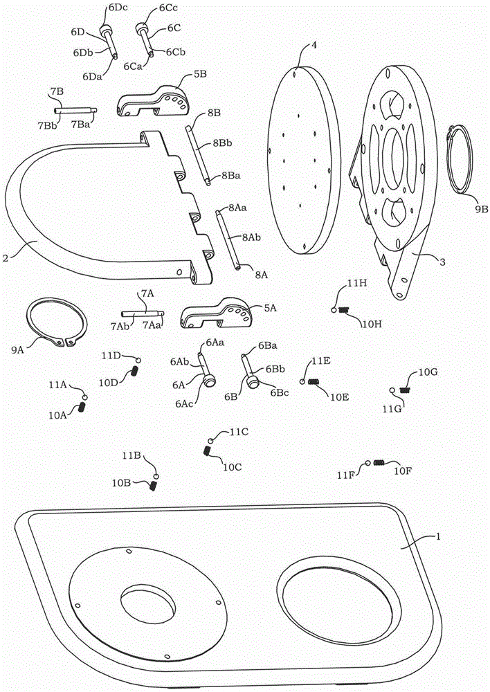
[0044] see Figure 1A , Figure 1B , Figure 1C As shown, a three-axis integrated fiber optic gyro optical path assembly auxiliary device includes a base 1, a horizontal rotating plate 2, a pitch rotating plate 3, an angle rotating plate 4, an A angle positioning block 5A, a B angle positioning block 5B, A Angle Positioning Shaft 6A, B Angle Positioning Shaft 6B, C Angle Positioning Shaft 6C, D Angle Positioning Shaft 6D, A Short Shaft 7A, B Short Shaft 7B, A Long Shaft 8A, B Long Shaft 8B, A Shaft Circlip 9A , circlip 9B for the B axis, the first pressure brake combination, and the second pressure brake combination; wherein, the first pressure brake combination consists of four compression springs 10A, 10B, 10C, 10D and four steel balls 11A, 11B, 11C, 11D, the second pressure brake combination is made up of four compression springs 10E, 10F, 10G, 10H and f...


PUM


Abstract

The invention relates to an optical path assembly auxiliary device of a three-axis integral optical fiber gyroscope. In the optical path assembly auxiliary device, a horizontal rotary plate is connected with a base by a clamping spring through a shaft A, the horizontal rotary plate can rotate relative to the base, the horizontal rotary plate is connected with an angle positioning block A through a short rotary shaft A, the horizontal rotary plate can rotate relative to the angle positioning block A, the horizontal rotary plate is connected with an angle positioning block B through a short rotary shaft B, the horizontal rotary plate can rotate relative to the angle positioning block B, a pitch rotary plate is connected with the horizontal rotary plate through a long rotary shaft A and a long rotary shaft B, the pitch rotary plate can rotate relative to the horizontal rotary plate, an angle rotary plate is connected with the pitch rotary plate by a clamping spring through a shaft B, the angle rotary plate can rotate relative to the pitch rotary plate, and the angle rotary plate is provided with a hole matrix for mounting and fixing a three-axis integral optical fiber gyroscope body. The optical path assembly auxiliary device aims to provide fixing equipment and gesture adjusting equipment for the assembly of the optical path of the three-axis integral optical fiber gyroscope, the assembly efficiency of the optical path is improved, and the batch production of the gyroscope is promoted; additionally, the risks of breakage of an optical device tail fiber and damage of an optical device, due to false operation of operators, are reduced during the optical path assembly process, and the qualified rate of the gyroscope in production is improved.

Description

technical field [0001] The invention relates to a three-axis integrated fiber optic gyroscope, more particularly, a three-axis integrated optical fiber gyroscope optical path assembly auxiliary device. Background technique [0002] Fiber optic gyroscope is a sensitive device for angular velocity measurement. The single-axis FOG can only measure the angular velocity in a single direction along the FOG axis. In practical applications, three single-axis fiber optic gyroscopes are often installed on the same body structure in an orthogonal manner to form a gyroscope inertial group, so as to realize the measurement of angular velocity in three directions in space. The gyro inertial group composed of three single-axis fiber optic gyroscopes in a pairwise orthogonal manner is usually large in size and weight, and is not suitable for air-to-air missiles, torpedoes and other weapons with small diameters. For this type of weapon, the miniaturization and light weight of the inertial ...

Claims


Application Information

Patent Timeline
Patent Type & Authority Applications(China)
IPC IPC(8): G01C19/72G01C25/00
Inventor 高峰刘朝阳杨清生阚宝玺张振华许保祥隋国生赵鹤
Owner BEIJING AEROSPACE TIMES OPTICAL ELECTRONICS TECH
Why Eureka
Try Eureka