
Positive pressure leak hole calibration method

A positive pressure leak and leak technology, which is applied in the direction of detecting the appearance of fluid at the leak point, using the liquid/vacuum degree for liquid tightness measurement, etc. The problems of high technical content of calibration and calibration devices are solved, so as to achieve the effect of saving accumulation time, simple and easy calibration process, and short calibration time period.

Inactive Publication Date: 2013-02-27
NO 510 INST THE FIFTH RES INST OFCHINA AEROSPAE SCI & TECH
View PDF4 Cites 6 Cited by
  • Summary
  • Abstract
  • Description
  • Claims
  • Application Information

AI Technical Summary

Problems solved by technology

[0003] The disadvantage of this method is that during calibration, the calibration device is complicated, and the calibration device needs an exhaust system, a calibration system, and a measurement and control system. The calibration device has high technical content, is expensive, and has high requirements for researchers and operators.
Secondly, only the constant pressure method is used to directly calibrate the positive pressure leak, and the calibration range of the constant pressure method is narrow
Again, it cannot be used for large-scale calibration on site, and can only be used in the laboratory

Method used


Image

  • Positive pressure leak hole calibration method
  • Positive pressure leak hole calibration method
  • Positive pressure leak hole calibration method

Examples


Embodiment 1

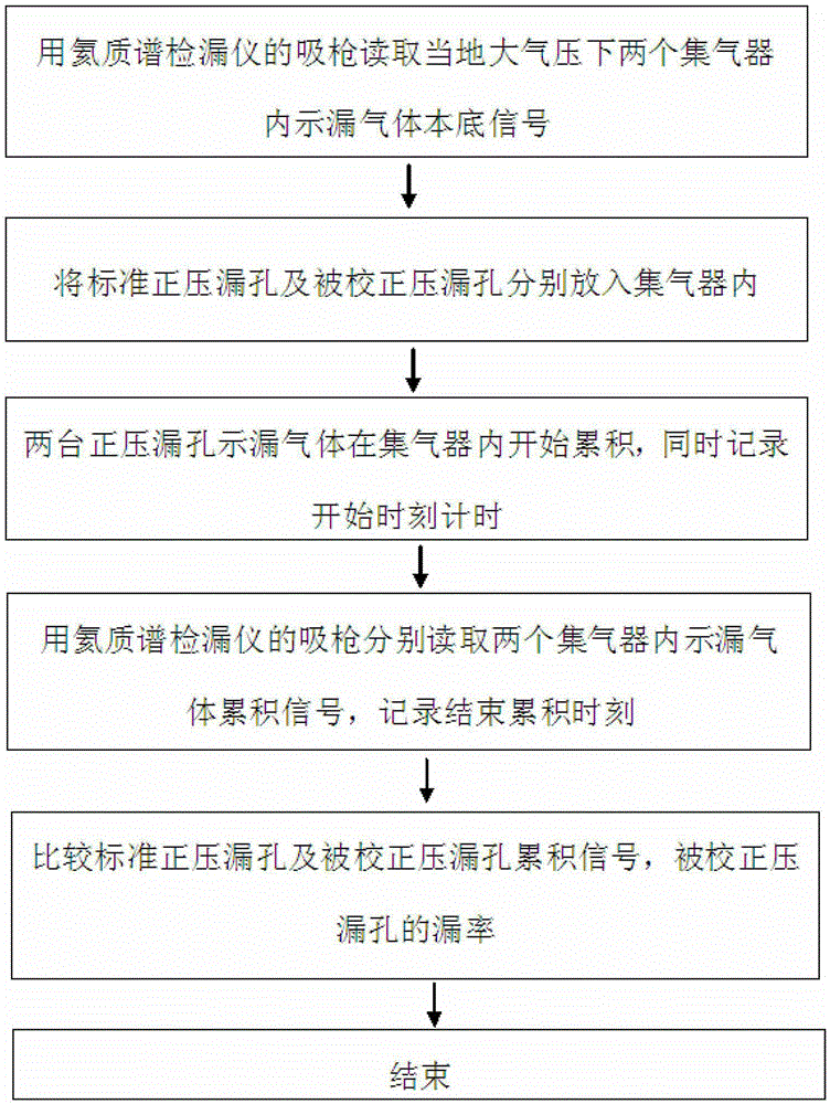
[0025] Such as figure 1 As shown, a method for calibrating a positive pressure leak, the steps of the method are as follows:

[0026] Step 1. Preheat the helium mass spectrometer leak detector for 3 hours, respectively introduce local air into the two gas collectors, and then close the two gas collectors;

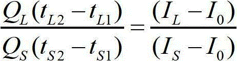
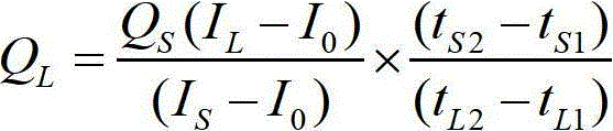
[0027] Step 2. Insert the sniffer gun of the helium mass spectrometer leak detector into any gas collector, and read the background signal I of the leaking gas helium in the gas collector under the local atmospheric pressure through the helium mass spectrometer leak detector. 0 =1.05×10 -7 Pa.m 3 / s;

[0028] Step 3. Put the standard positive pressure leak and the calibrated pressure leak into two gas collectors respectively; wherein, the standard positive pressure leak and the calibrated pressure leak are of the same type, and the standard positive pressure leak is of the same type. The leak rate is known, but the leak rate of the calibrated leakage hole is unknown;

...


PUM


Abstract

The invention discloses a positive pressure leak hole calibration method, which belongs to the technical field of vacuum measurement. The method comprises the following steps that (1) a helium mass spectrum leak detector is preheated, and local air is respectively led into two gas collectors; (2) background signals IO of helium gas as leak indication gas in the gas collectors are read by the helium mass spectrum leak detector; (3) a standard positive pressure leak hole and a positive pressure leak hole to be calibrated are respectively put into the two gas collectors; (4) the leak indication gas flowing from the two positive pressure leak holes is accumulated in the gas collectors, and the start time tS1 and tL1 is respectively recorded; (5) after the leak indication gas flowing from the two positive pressure leak holes is accumulated in the gas collectors for a period of time, accumulating signals IS and IL of the leak indication gas in the two gas collectors are respectively read by the helium mass spectrum leak detector, and the end time tS2 and tL2 is recorded; and (6) the leak rate of the calibrated positive pressure leak hole is calculated. The method has the advantages of simplicity, easiness in implementation and low cost and can be applied to calibrated positive pressure leak holes with different orders of magnitude, the calibration range is extended, and the calibration efficiency and the calibration practicability on site are increased.

Description

technical field [0001] The invention relates to a method for calibrating a positive pressure leakage hole, which belongs to the technical field of vacuum measurement. Background technique [0002] In the document "Design of constant pressure positive pressure leak calibration device, "Journal of Vacuum Science and Technology", No. 5, 2007, pages 442-446", a method of calibrating positive pressure leaks using constant pressure method is introduced. Hole method, this method is to directly introduce the leakage gas flowing out of the positive pressure leak hole into the variable volume chamber of the positive pressure leak calibration device of the constant pressure method, and change the displacement of the piston to increase the volume of the variable volume chamber to ensure the variable volume The principle of constant indoor pressure is used to obtain the calibration of positive pressure leaks. [0003] The disadvantage of this method is that during calibration, the calib...

Claims


Application Information

Patent Timeline
IPC IPC(8): G01M3/20
Inventor 赵澜冯焱成永军张瑞芳盛学民张涤新
Owner NO 510 INST THE FIFTH RES INST OFCHINA AEROSPAE SCI & TECH
Learn More